
Table of Contents
1) Introduction
2) Printer un-boxing and installation
3) Getting to know your TRILAB DeltiQ 2 printer
4) Making your first DeltiQ 2 print
5) Cheat sheet – standard printing procedure
6) How to use the DeltaControl display and application
7) How to use the WebControl online interface
8) Installing the printer on your own
9) Printer service procedures
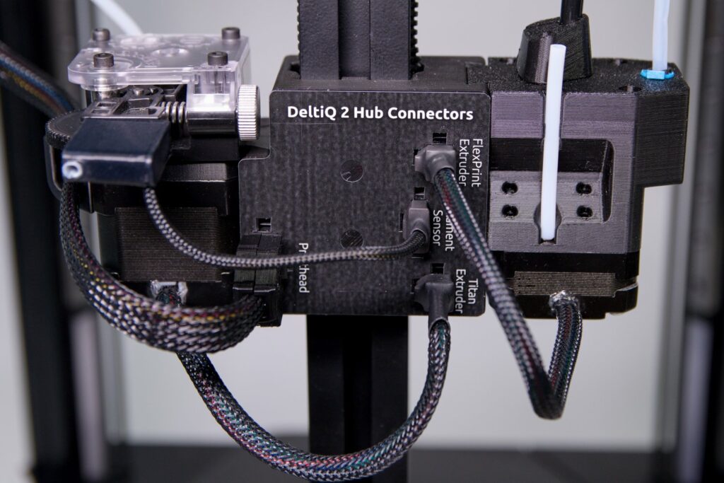
Swapping the Titan and FlexPrint extruders (FlexPrint 2)
To interchange the extruders use the following instructions. The procedure for disconnecting the Titan extruder and connecting the FlexPrint extruder is shown below. For swapping from FlexPrint to Titan extruder, apply the reverse sequence.
Tip: For videomanual use this link: https://youtu.be/QiVbjAZuUf8
Caution: Always swap the extruders with the filament removed.
Removing the Titan extruder
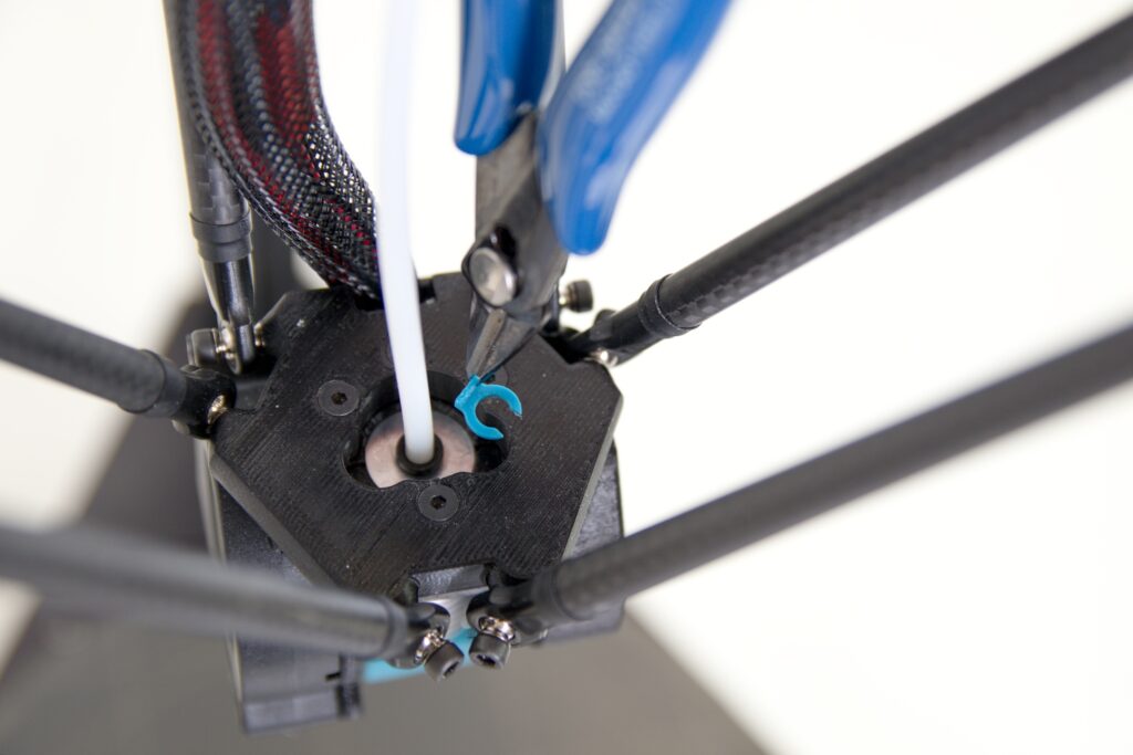
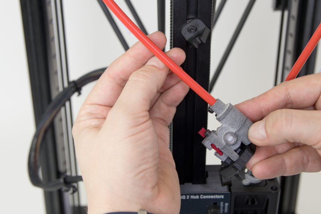
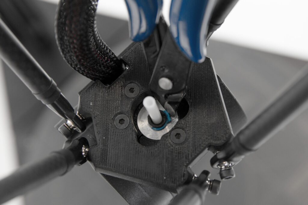
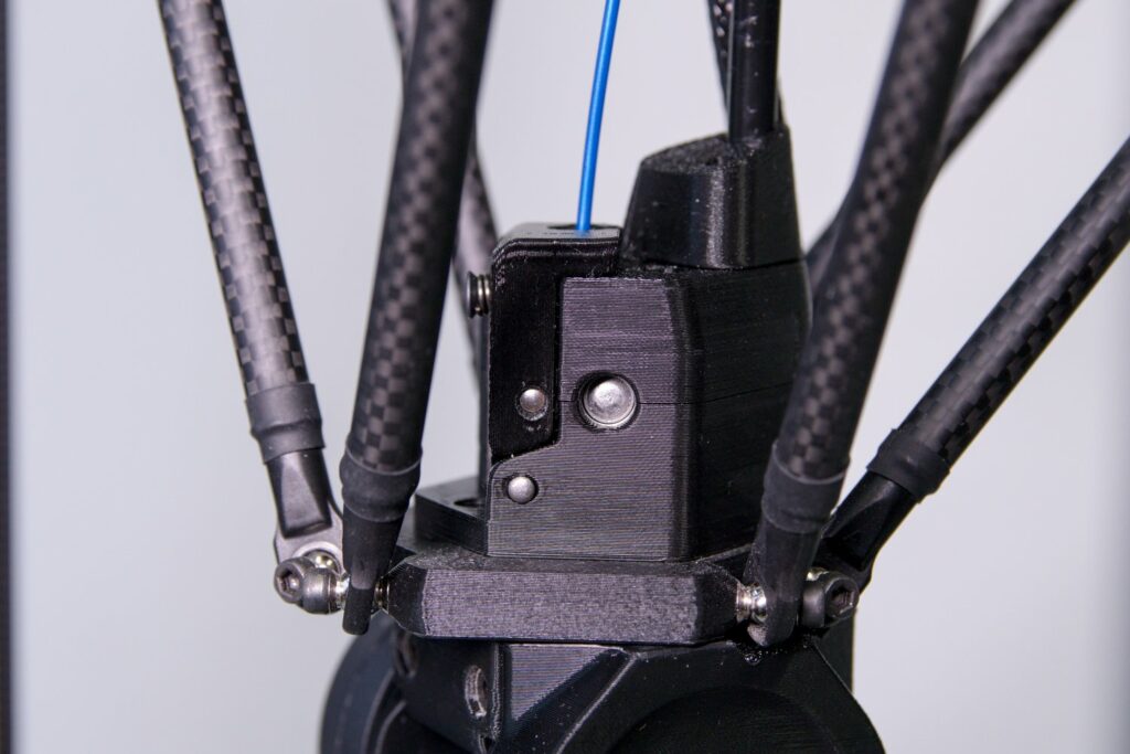
First, remove the blue safety ring from the bowden cable on the print head.
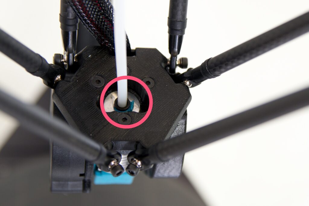
You can use the supplied pliers and remove the ring from the special recess in the top profile of the print head.
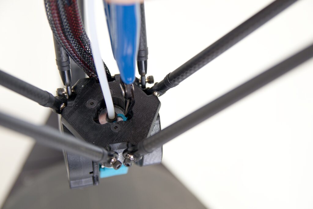
Then, press down on the black bowden cable lock with the pliers.

This will release the bowden cable on the print head side.

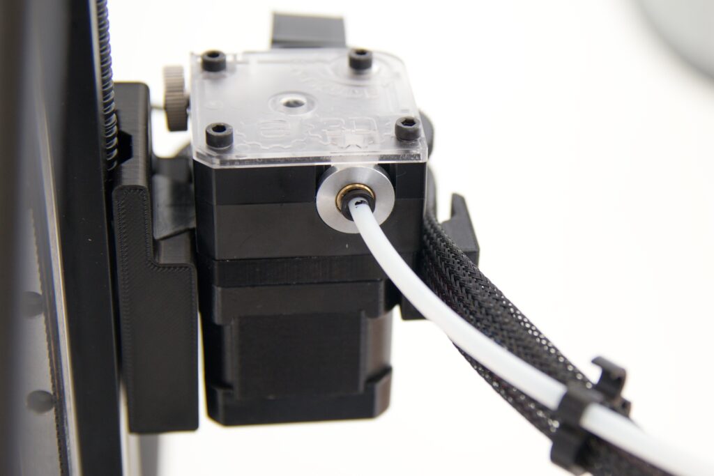
Now repeat the procedure for the Titan extruder. Remember to remove the safety blue ring first.

Then press the black line lock the same way and remove the Bowden cable from the extruder.
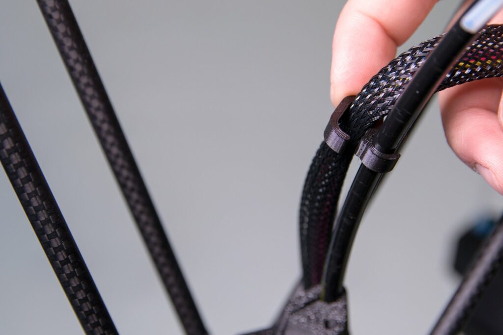
The wiring is also attached to the harness at several locations by means of printed clips. Carefully remove the Bowden cable from the clips.

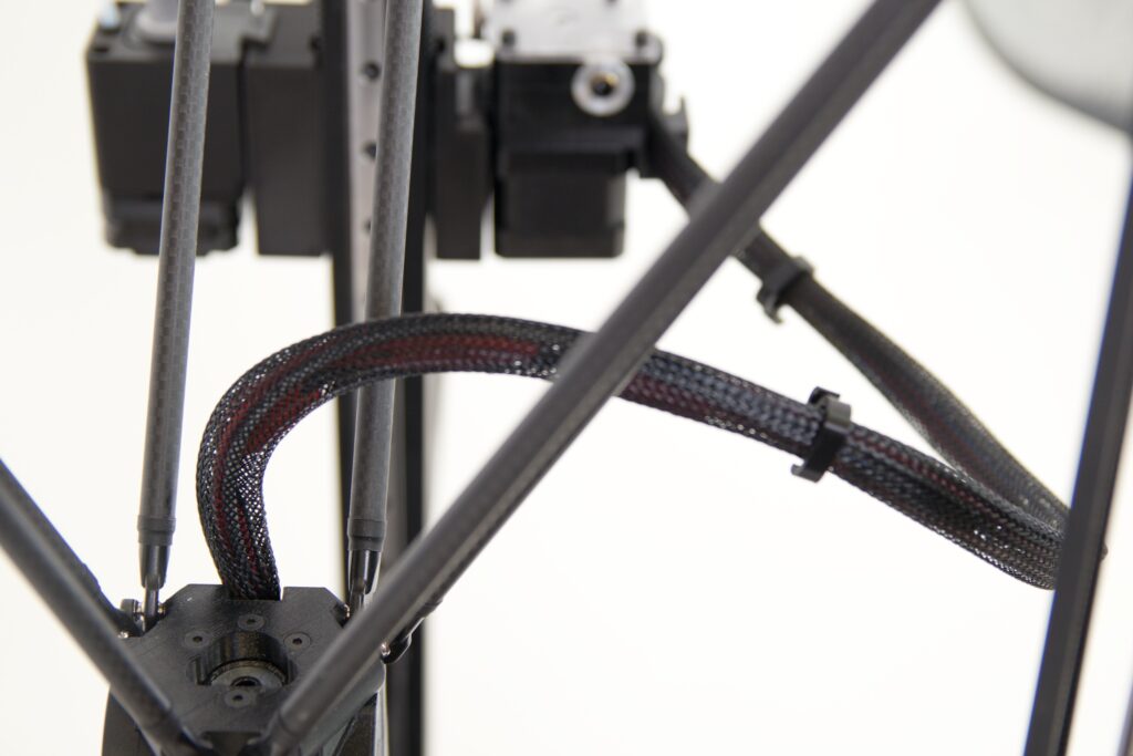
Tip: To prevent your bowden cable from getting lost, place it in one of the vertical profiles.

Connecting FlexPrint extruder
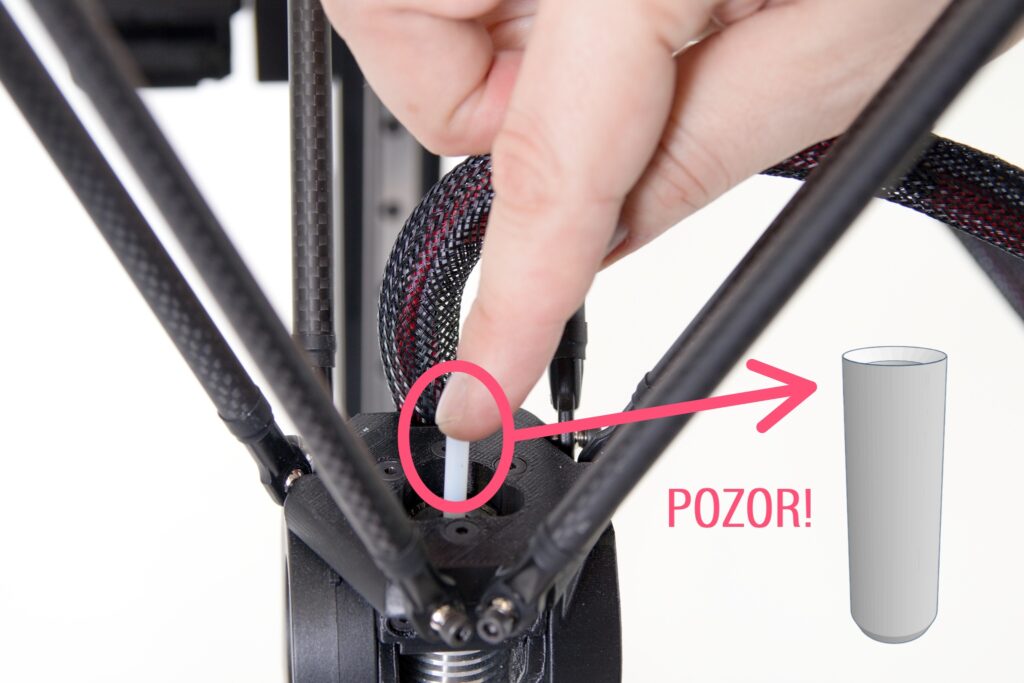
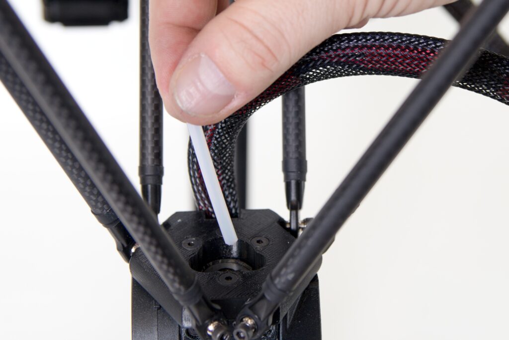
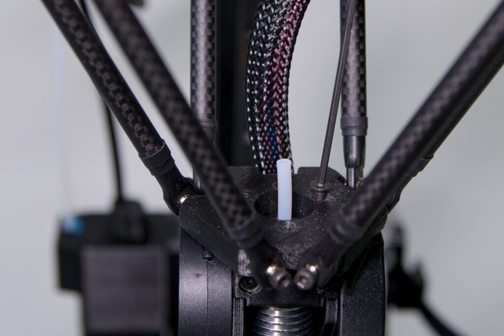
Remove the short Teflon tube from the FlexPrint extruder holder.

Place it in the newly accessible hole in the print head. It’s fine if part of the tube protrudes from the print head.
Note: The tube is not trimmed equally at both ends. The correct orientation is such that the tube rises through the head with the pointed end first (picture the point of a crayon) and ends at the top with a cone-like cut.

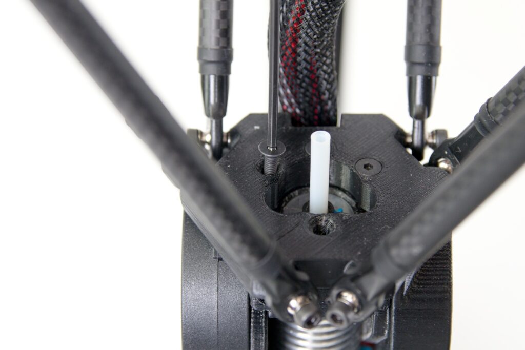
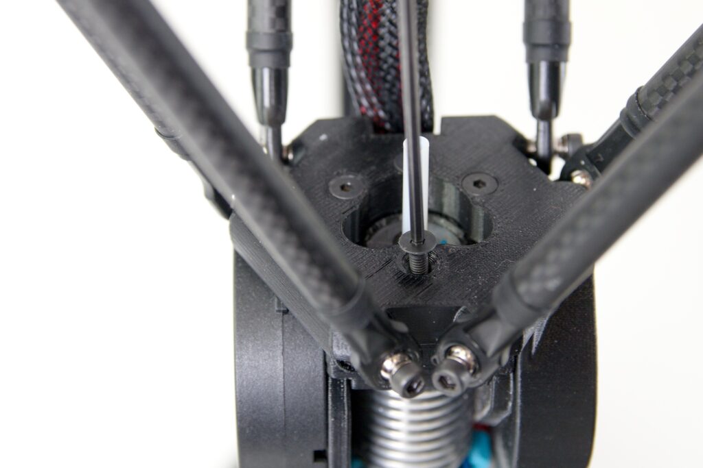
After placing the tube through the head, try to pull it out slightly. You will not be able to remove it, but the Bowden Lock will create a space to re-apply the blue safety ring.

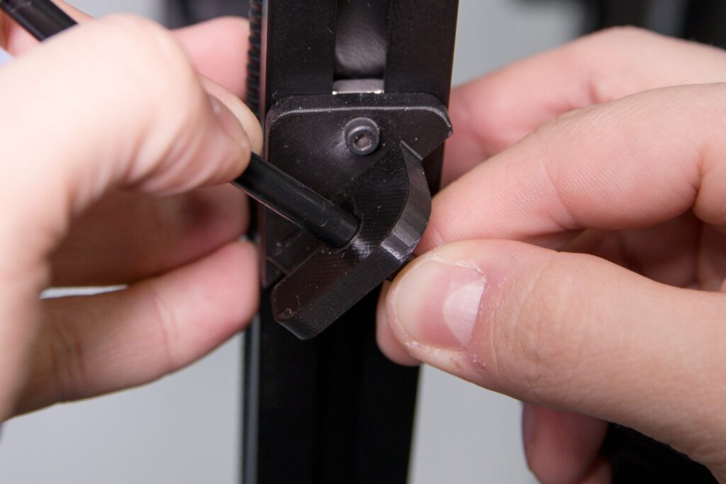
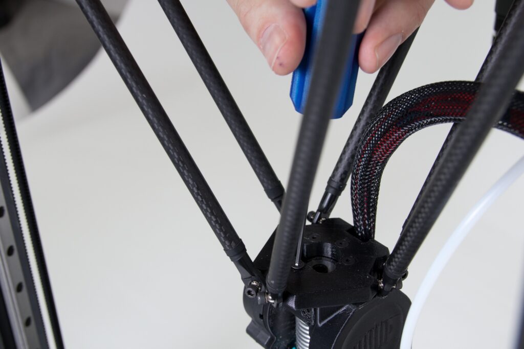
Using the supplied Allen key, remove the front screw from the print head (shown in the following photo with the printer facing the user).

Second, remove the left rear bolt.
Place the loosened screws in the bracket on the FlexPrint extruder. This will prevent you from losing them.

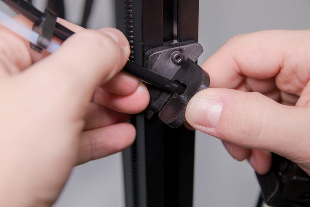
Remove the moving part of the FlexPrint extruder from the bracket in the rear vertical profile of the printer. It should come off with a slight click.

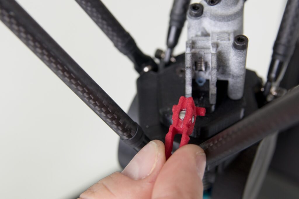
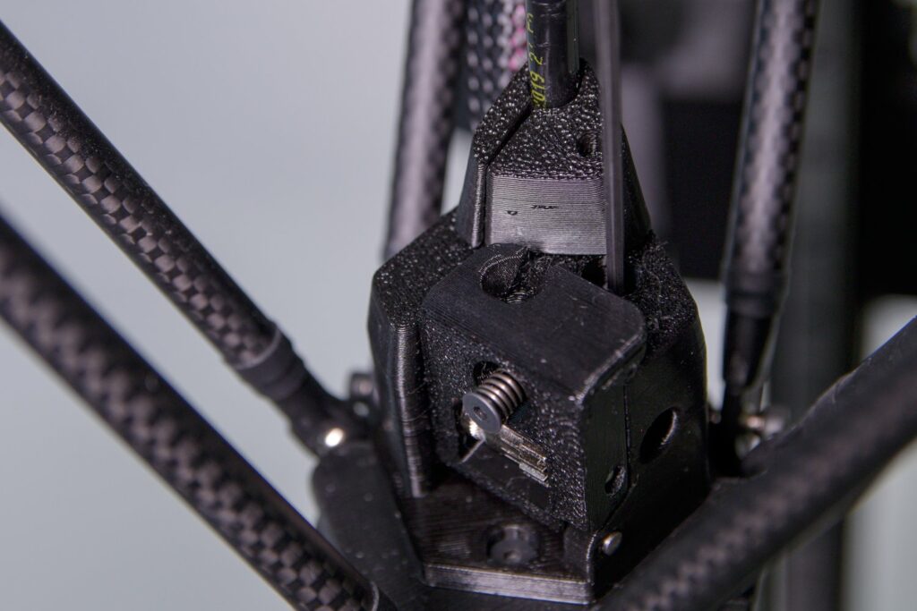
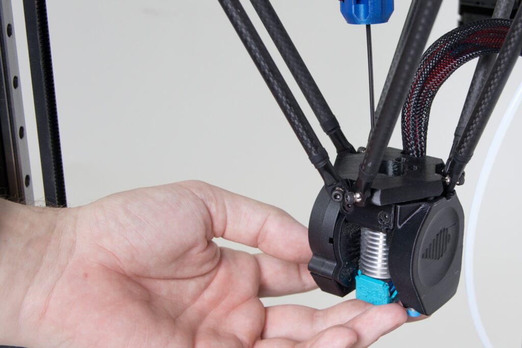
Put the head part of the extruder into your hand. Next, you will temporarily remove the red piece which is snug against the filament wheel.

Press the two tabs together on the red part of the extruder head and swing it towards you. Then remove the entire red piece.

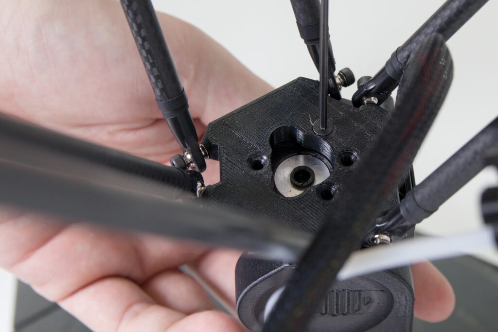
Position the extruder head so that the extruder’s head screws are located above the holes after the screws have been removed.

Screw the FlexPrint extruder head to the print head using the Allen key provided.

Verify that the assembly is properly fitted by aligning the Teflon tube orifice with the rest of the FlexPrint extruder head. The figure also clearly shows a cross cut section of the tube confirming the correct orientation that we went over in the previous steps.

Now re-install the pressure roller (the red piece we removed). Hold the tabs between your fingers and verify that the two perpendicular tabs on the opposite side of the red section are pointing downwards, not upwards.
Place the red part that corresponds to the matching part of the extruder body head as shown in the following figure. Now the extruder is ready to insert filament.
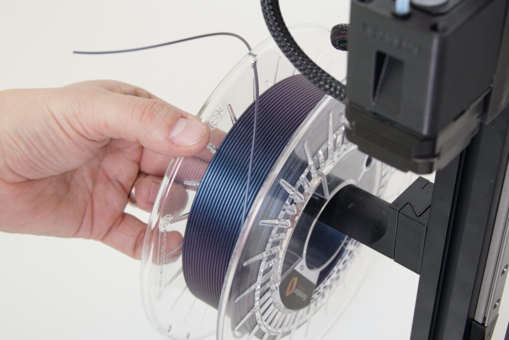
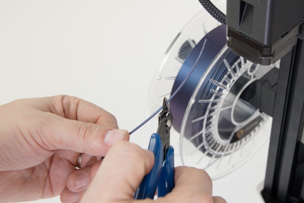
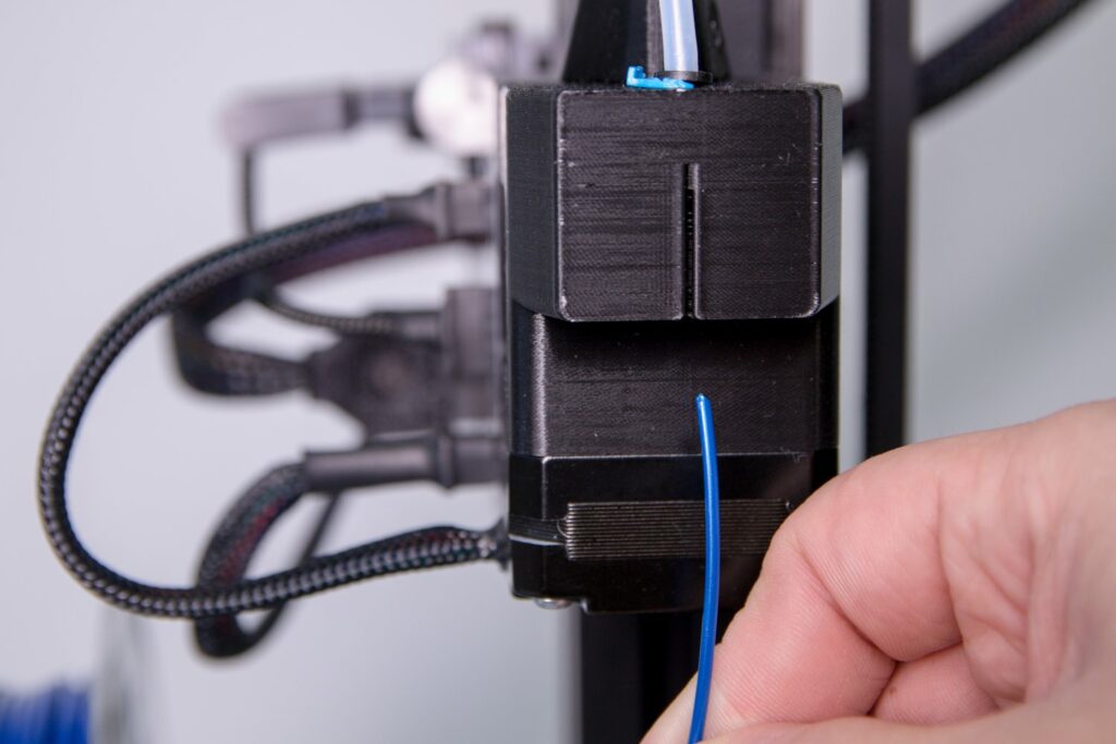
Next, we’ll prepare the filament to be applied through the FlexPrint extruder. It will have a similar procedure to that of the Titan extruder. Remove the string from the secured position in the spool eye and trim it with the supplied pliers at a 45° angle.
Feed the line through the hole of the FlexPrint extruder motor unit labeled FILAMENT as shown in the following figures. The motor does not have any components in the filament’s path and should go smoothly when feeding the filament.

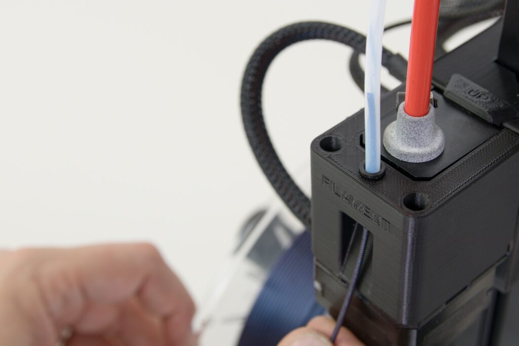
Push the filament through the entire bowden cable so that it sticks out at the other end.
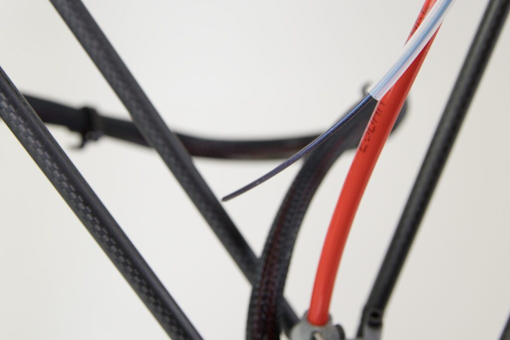
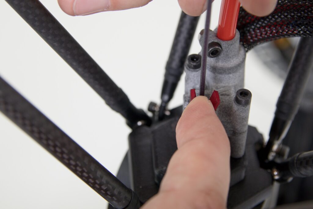
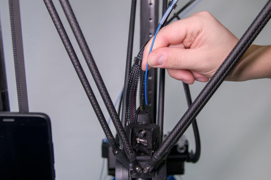
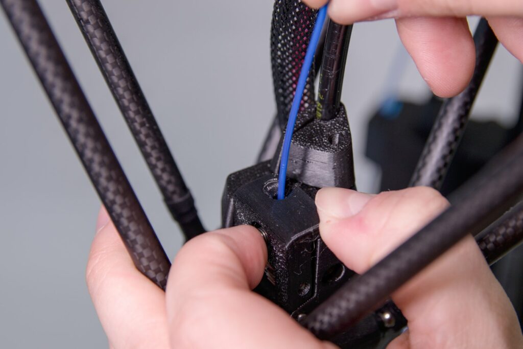
Feed the free end of the filament into the head of the FlexPrint extruder as shown below.


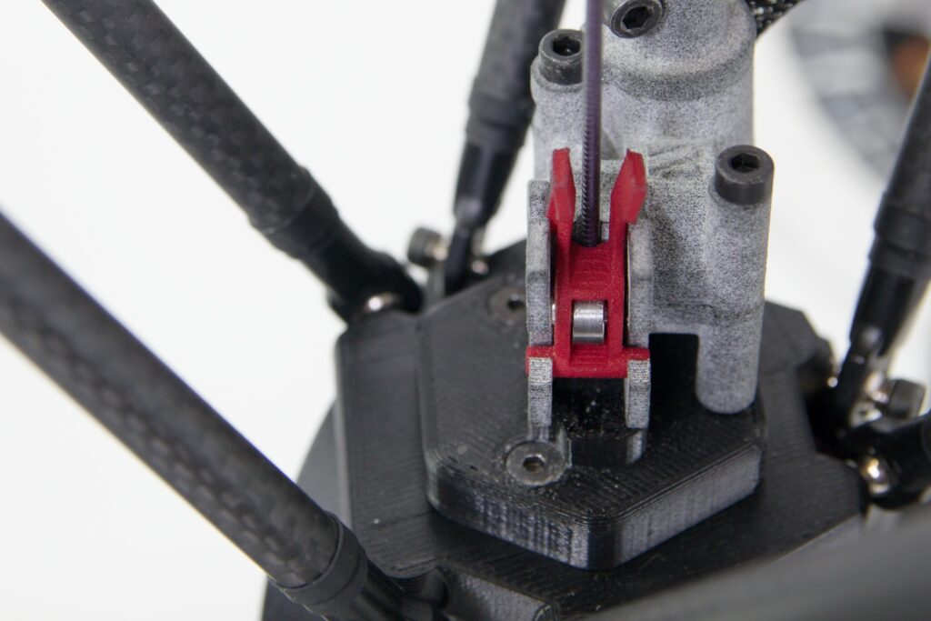
Press the red tabs of the head’s red hinged piece together and place the entire piece in an upright position. This fixes the pressure wheel in place. It is good to insert a finger between the tabs to verify the correct positioning (snapping-in) of the hinged part.

After completing all of these steps, the printer is ready to print using the FlexPrint extruder.
Caution: After starting the printer, the first thing you should do is to run DeltaControl’s user-defined FlexPrint LOAD FILAMENT macro.
FlexPrint 2 extruder connection
First, disconnect the Titan extruder as described above. Remove the short Teflon tube from the FlexPrint 2 extruder holder.
Place it in the newly accessible hole in the printhead. It’s OK that a part of the tube will protrude from the print head.

Caution: The ends of the tube are not the same at both ends. The correct orientation is such that the tube enters the head with the trimmed end (similar to a crayon) and is terminated at the top with the funnel cutout.
After placing the tube correctly, try to pull it out slightly. You won’t be able to, but the bowden cable lock will create a place to return the blue retaining ring to.
Using the Allen key provided, remove the front screw from the printhead (indicated in the following photo with the printer facing the user).
Second, remove the right rear bolt.
Place the loosened screws in the holder on the FlexPrint extruder. This will prevent them from being lost.
Lightly click the moving part of the FlexPrint extruder out of the holder in the rear vertical profile of the printer.
Tip: To make it easier to handle the extruder head with your free hand, grasp the cable harness in the braid and slide it to the side.
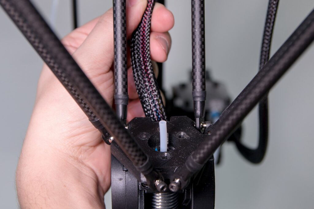
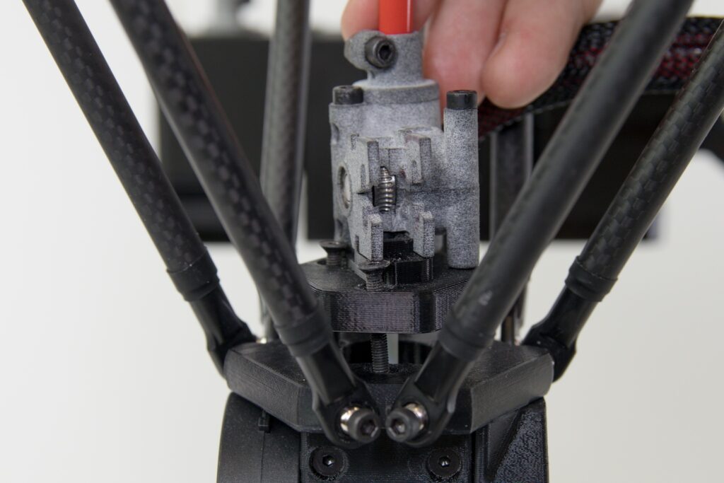
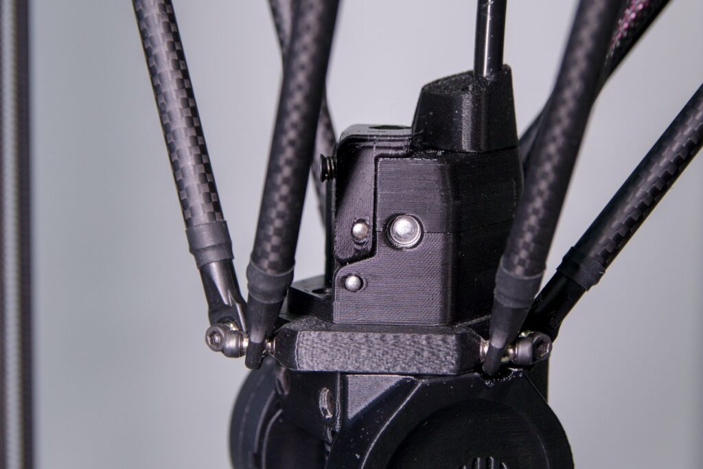
Grasp the extruder head and position it so that the extruder screws are above the holes after the screws have been removed.
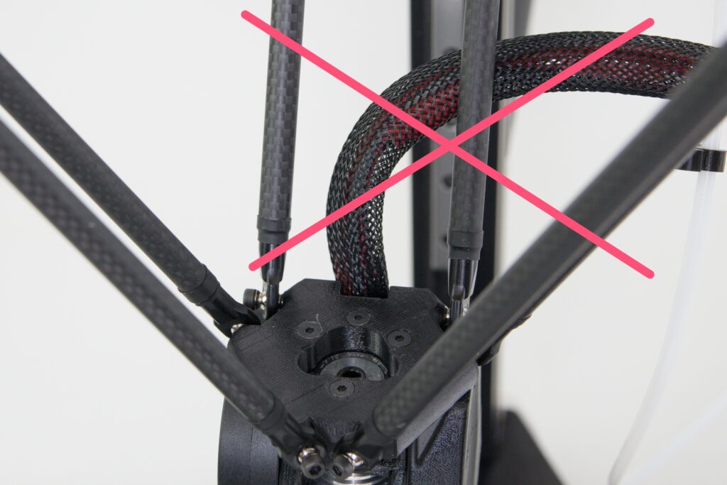
Caution: The FlexPrint 2 extruder must enter the space above the print head in the same way as the cables leading to the print head, ie. between the back and right pair of arms. Any other way is not safe and could damage the printer.
Place the extruder head on the Teflon tube.
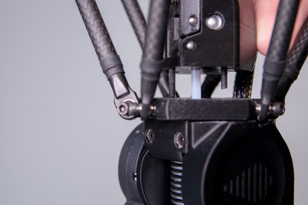
Use the supplied Allen key to screw the FlexPrint 2 extruder head to the printhead.
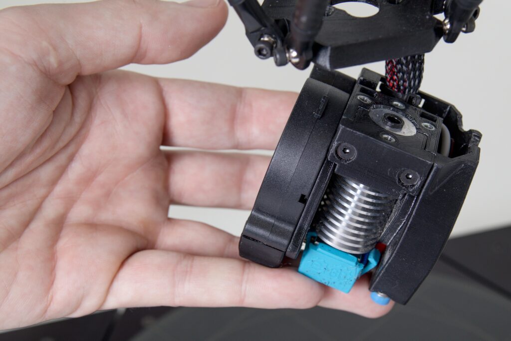
You will be able to tell that the extruder is correctly attached to the print head by there being no gap between the extruder and the head and that the extruder does not move.
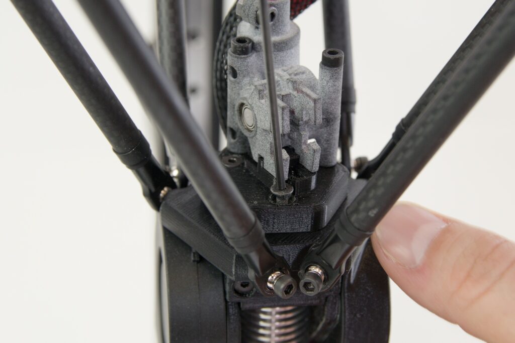
Use the printed handle to attach the cable harness in the black braid to the black extruder guide.
Snap the black extruder guide into the bracket on the rear vertical profile.
Prepare the filament for loading into the FlexPrint extruder. The preparation procedure is similar to the Titan extruder. Remove the filament from the secured position in the eye of the spool and cut it with the supplied pliers at an angle of approximately 45°.
Insert the string through the hole in the motor section of the extruder as shown in the following images. The motor part does not contain any components in the filament path, so it does not put up any resistance during insertion.
Gradually push the string through the entire bowden line so that it protrudes from the other end.
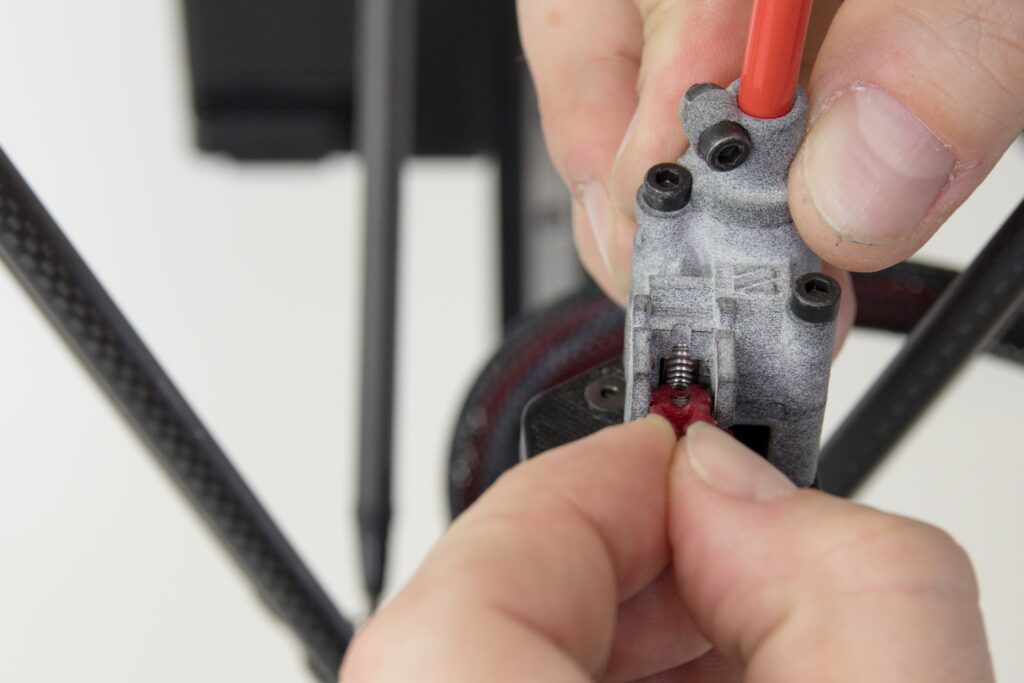
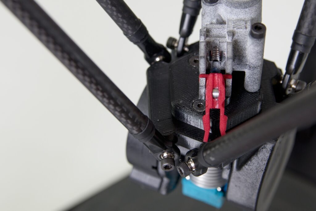
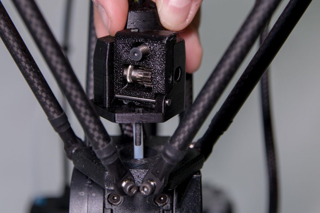
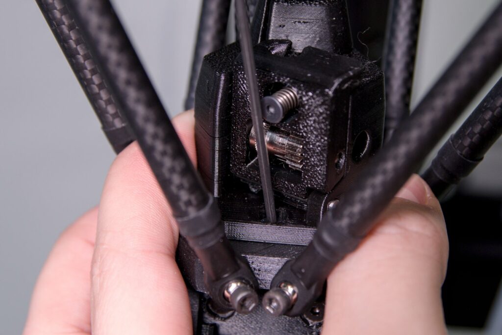
Insert the free end of the filament into the hole above the gear-looking wheels.
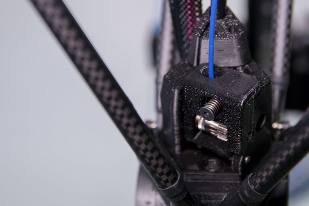
Push the spring screw with your index finger and use your thumb to open up a part of the pressure mechanism. Then use your right hand to insert the filament between the feed wheels of the extruder and then release the pressure mechanism.
The surfaces of the pressure part and the extruder must be flush, they must not deviate from each other.
Caution: First, run the LOAD FILAMENT user macro for the FlexPrint extruder in DeltaControl after starting the printer.
Replacing the Print Head
The print head can be replaced very simply. It is thus possible to have different configurations of the print heads (with a different nozzle or modified heating element).
Caution: Always replace the print head with the printer turned off and the filament removed.
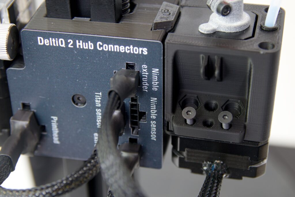
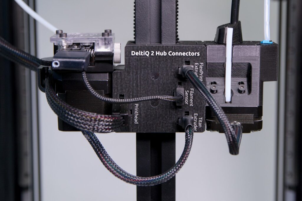
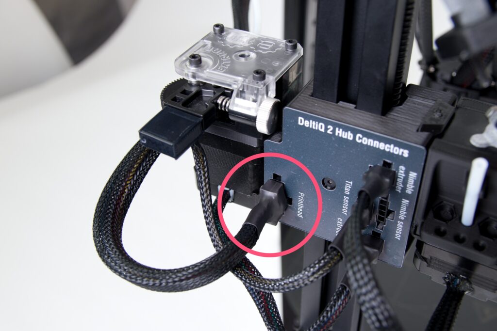
First, remove the printhead connector (labeled Printhead) from the hub. It is necessary to press the tab on the side of the connector.

Depending on which extruder you have connected to the printhead, use the relevant section (Swapping Titanium and FlexPrint extruders) to remove the Bowden cable or FlexPrint extruder head from the printhead.
In any order, loosen all of the screws on the print head. While unscrewing the last, hold the print head down to prevent it from falling.

Then remove the print head. The machine is ready to have another print head installed. Use this part of the manual, in reverse order, to re-install it.

Caution: Please pay attention to the position of the wiring harness when replacing the printhead. The wiring harness must extend between the two rear arms and never sideways.

Afte the replacement, make the change also in the WebControl and do the temperature calibration as described in the Nozzle Replacement section below points 16-20. For more information see the chapter WebControl/Settings.
Cleaning the nozzle (cold pull)
Caution: This procedure requires you to perform some steps in rapid succession. Please read this manual in advance and make sure you understand those steps.
If the filament flows only slightly through the nozzle, it is probably clogged. It can be cleaned by a cold pull. This method uses the partial solidification of the filament in the nozzle to its advantage and removes any stuck impurities.
Prepare your pliers and approx. 50 cm of light colored PLA strings (it will be easier to control dirt pulled out of the nozzle).
If filament is loaded in the print head, remove it now.
Use the pliers to loosen the filament bowden cable attachment to the print head (if using a Titan extruder) or unscrew the FlexPrint extruder head and remove the short Teflon tube from the print head (using a FlexPrint extruder). In any case, the fact that there is nothing blocking the printhead from above is our starting point for further actions.
Heat the nozzle to 210°C using the online control interface or the DeltaControl display.
Cut about 50 cm of filament at a 45° at the end with the pliers and straighten the last 10 cm.
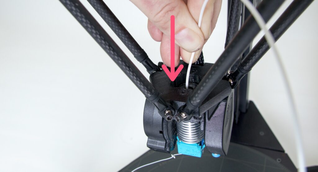
When the nozzle temperature reaches 210°C, insert the trimmed piece of filament into the print head. Molten filament should start to flow out of the nozzle.
Tip: If the filament does not come out of the nozzle at all, the nozzle is probably clogged completely and the cold pull method is unlikely to work. In this case we recommend replacing the nozzle with a new one.
Catuion: For the next steps, hold the print head with your other hand when loading the filament. This is to prevent the print head from moving and causing possible damage to the printer electronics by randomly moving the print head.
Using the DeltaControl display or web interface, reduce the nozzle temperature to 90°C. Press the filament with a moderate but constant pressure into the print head until the nozzle temperature drops below 160°C.
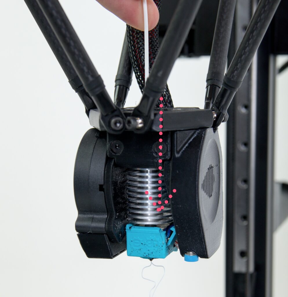
When the temperature drops to 90°C, the filament in the nozzle is relatively stiff but still slightly elastic.
Caution: At this point, do not leave the filament in the nozzle longer than necessary and proceed to the next step immediately.
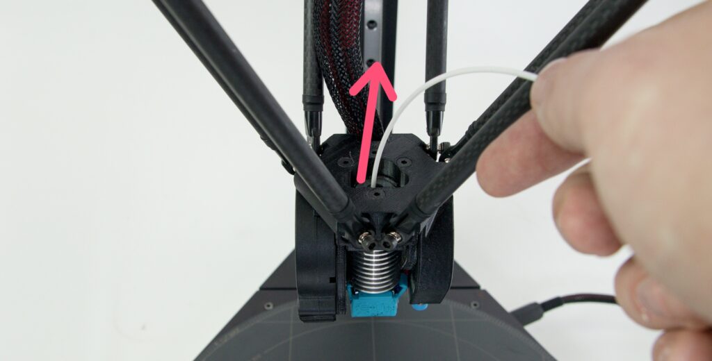
Hold the free end of the filament by one hand, the print head with the other hand and rip out the filament with a quick upward movement.
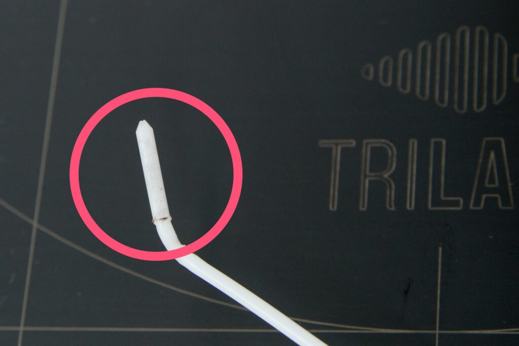
Check the part of the filament that you removed from the nozzle. If the procedure was done correctly, pieces of dirt from the nozzle should be visible at the end of the extracted filament. There is also an impression of the internal shape of the nozzle.
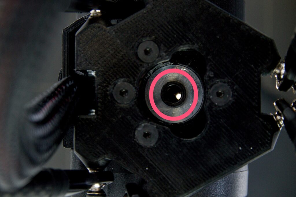
From above (and illuminated from below) it is possible to check that the nozzle is clear of any debris – if the procedure is successful, you can see through the nozzle. For optimum efficiency, we recommend repeating the entire nozzle cleaning procedure again.
After the nozzle is clear, slide the Bowden cable back into the printhead (or put the FlexPrint extruder head) back into place and secure it with the blue lock.
Nozzle replacement
The process of replacing the nozzle is not complicated, but is performed at temperatures up to 300°C. Therefore, be very careful, read the entire manual properly and make sure you do understand all the instructions. If not, contact the servise department. Before following the procedure below, unload the filament from the printhead using macro Unload Filament on the Prepare page.
- Prepare the new nozzle, torque wrench, adjustable pliers (or any pliers)
- Make sure the printhead is cooled below 50°C (status LED diode is white), if not, cool it
- Unscrew the screw from the side blower
- Carefully remove the blower by pulling it down while holding the printhead with your other hand
- Carefully remove the blue silicone sock from the hotend (be aware of thermistor and heater wires)
- In the WebControl heat up the printhead to 300°C
- Fix the heatblock (aluminum cube) with the adjustable pliers and unscrew the nozzle by torque wrench
- Cool down the printhead below 50°C
- Screw on the nozzle with your fingers
- Heat upt the printhead to 300°C
- Fix the heatblock (aluminum cube) with the adjustable pliers and tight up the nozzle by torque wrench to hear at least 3 clicks
- Cool down the printhead below 50°C
- Make sure the hotend is straight and is not touching to any plastic part of the printhead
- Put on the blue silicone sock
- Put on and screw on the side blower
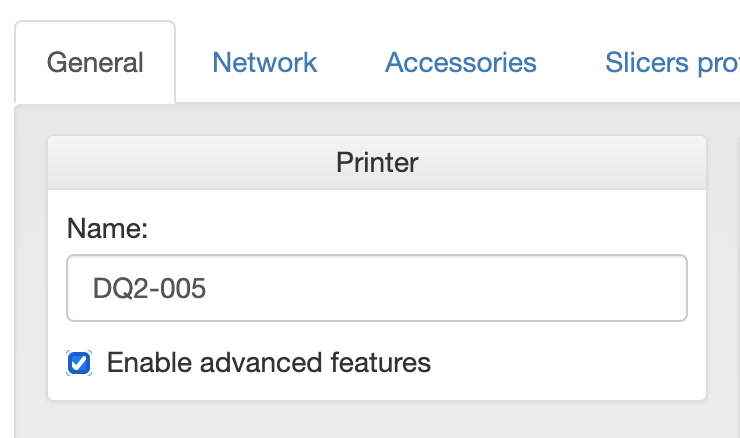
- On the page Settings check the Enable Advanced Features box
- Make sure the printhead is cooled below 50°C
- On the page Machine Control insert command: M303 H1 S220 (both upper and lower cases work), click on Send button and wait till there is an confirmation the temperature calibration was processed correctly – Auto tune heater 1 completed. This process might take several minutes, usually 5 to 6 minutes.
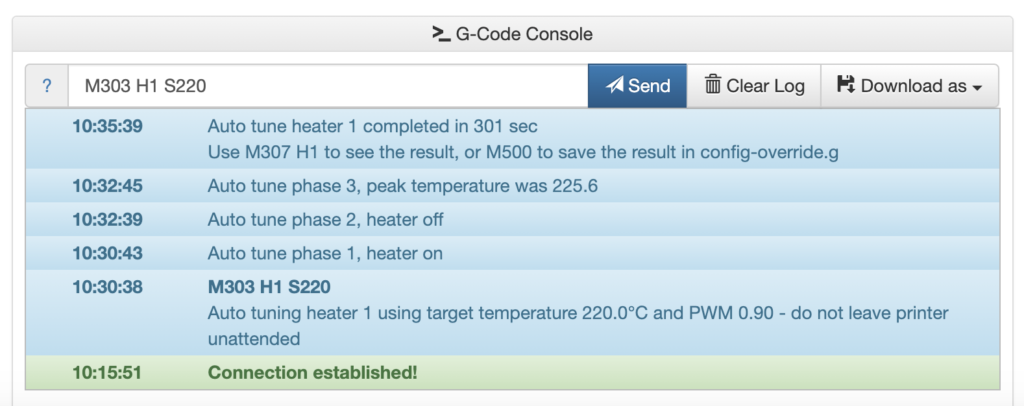
Caution: During the temperature calibration, the nozzle is very hot (more than 220°C), pay attention to your safety. Also do not perform any other action, the calibration will not run correctly.
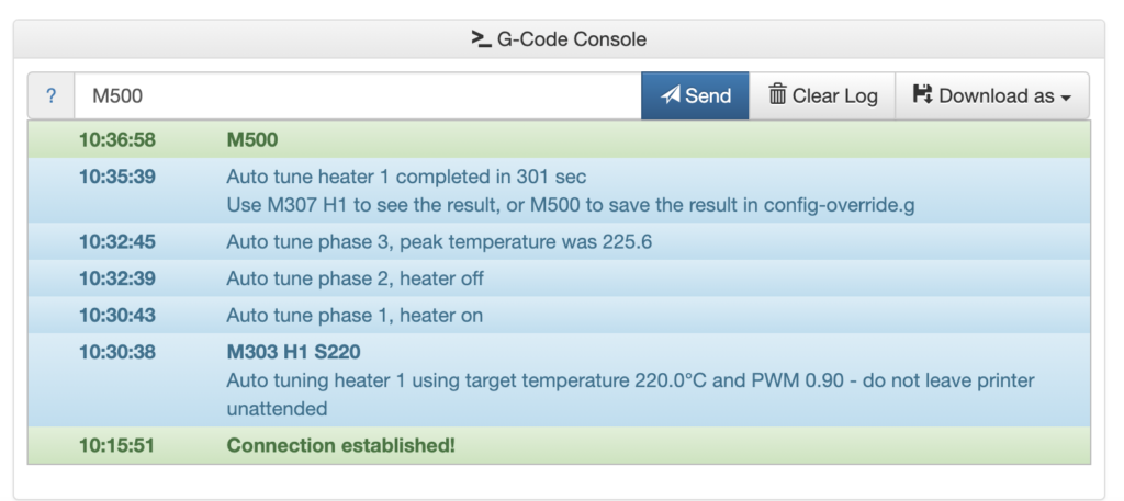
- Save the calibration results by inserting commad M500 and clicking on Send button
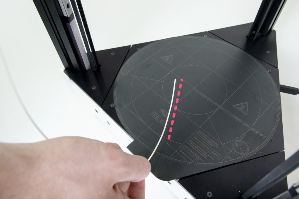
- Reset your Z offset and set the new correct height for the first layer