
Table of Contents
1) Introduction
2) Printer un-boxing and installation
3) Getting to know your TRILAB DeltiQ 2 printer
4) Making your first DeltiQ 2 print
5) Cheat sheet – standard printing procedure
6) How to use the DeltaControl display and application
7) How to use the WebControl online interface
8) Installing the printer on your own
9) Printer service procedures
1) Unboxing
Place the printer box on a solid and stable surface (ideally a table or workbench, or even on the ground). Remove the adhesive tape from the safety hinges and open the flaps on the front of the box.
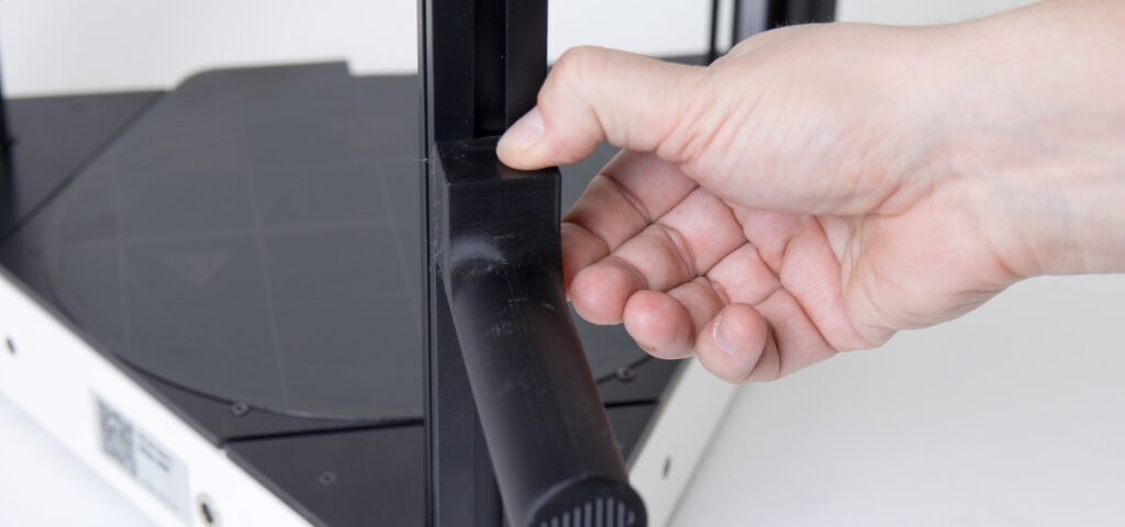
Then fold the lower and upper flaps of the box. Carefully but firmly hold the prepared printer by the vertical profile and pull it out of the box (which you will probably have to hold on to with your other hand).
Caution: Never handle the printer on the edge of a desk where it may fall.
Caution: If you have difficulty removing the box, get a friend to help you.
Warning: Never pull the printer by the connector hub located in the center of the vertical aluminum profile, as this may damage the printer.
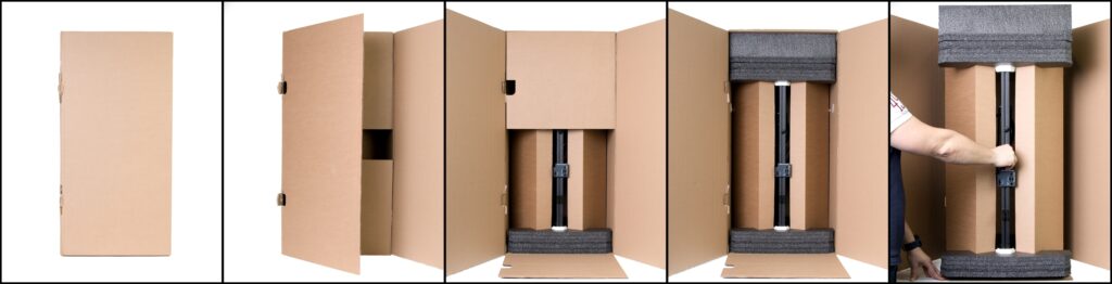
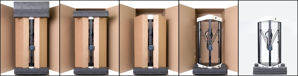
After removing the printer, remove the spacer foam from the top of the printer. The foam quantity depends on the printer variant ordered. When removing this foam, be careful not to bump the vertical boxes on the sides and cause them to collapse on each other.
After removing the foam, remove both of the vertical boxes.
Caution: One of the boxes is intentionally empty in the standard delivery, while the other box contains a number of accessories. Therefore, their weight varies greatly. In the second box however, there may be accessories supplied as part of your order.
After removing the accessory boxes, lift the printer to remove the box, and then lift the printer again (carefully grasping two of the side profiles) and remove the lower protective foam.
2) Printer accessories
One of the boxes supplied with the printer contains the standard accessories supplied with the printer. Unpack the box by tilting the front narrow side of the box and then lifting it up.

Please take care to note all the small accessories that may be overlooked in the dark foam.

The standard printer accessories supplied with one extruder (E3D Titan) include the following components (from the top left):
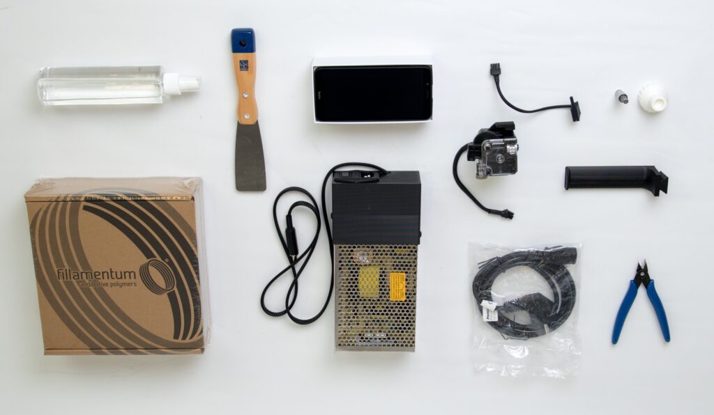
- IPA spray bottle
- Spatula for removing prints
- DeltaControl Display (Mobile Phone, may vary depending on version)
- Titan E3D Extruder with mounting construction
- Filament holder
- Filament sensor
- Hex bit for nozzle release/tightening
- Printed torque wrench for the hexagonal bit
- One pack of filament
- Power supply
- Power cable to the power supply
- Pliers for cutting and adjusting filament
If your printer comes with two extruders (E3D Titan and Zesty Nimble), the equipment is similar, but extended with the following parts:

- A Hexagonal spanner with a printed holder
- Two spare screws for the print head
- Two 55mm Teflon tubes (one is a spare)
- FlexPrint or FlexPrint2 extruder
3) Display installation
Place the printer on a stable surface so that you can easily access the entire internals of the machine.

Carefully remove the mobile phone from the box and remove the protective packaging.
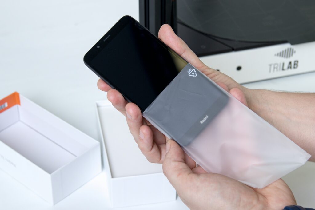
Place the phone in the charging station located on the left front profile of the printer.
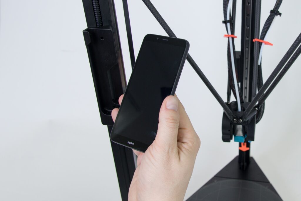
Caution: The only correct display position is perpendicular to the top of the printer. Placing the phone any other way may damage the charging station connector. Please handle the display with the exact same care when removing it.

You will know the display is placed properly in the station when you hear a slight click (similar to plugging the charging cable into the phone).
The display is firmly seated when it is inserted into the station. Be sure to remove it when transporting the printer.

4) Unlocking moving parts
During transport, the printer is protected by a set of security features to prevent damage to the machine during transport. The following chapter describes how to remove them.
Warning: If you do not remove all the security features as mentioned in this chapter, you may damage the printer after starting.
Tip: If you want to transport the printer again, you can perform the steps in reverse order to prepare the printer for transport. Do not throw away the locking elements.
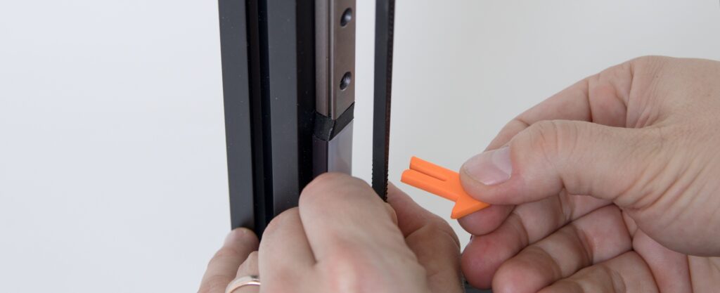
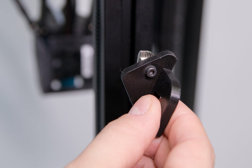
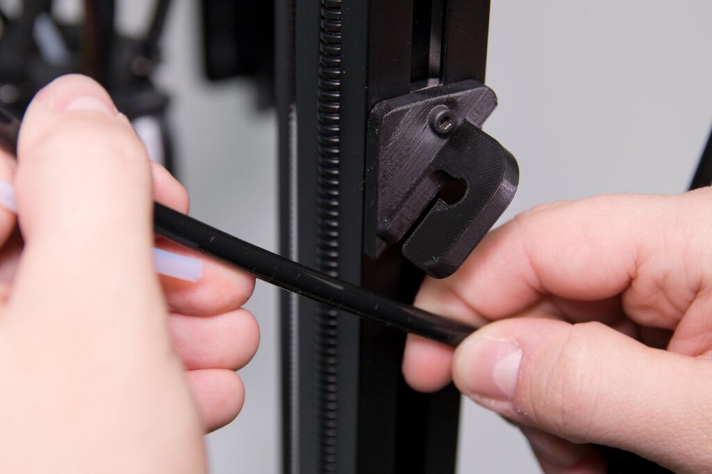
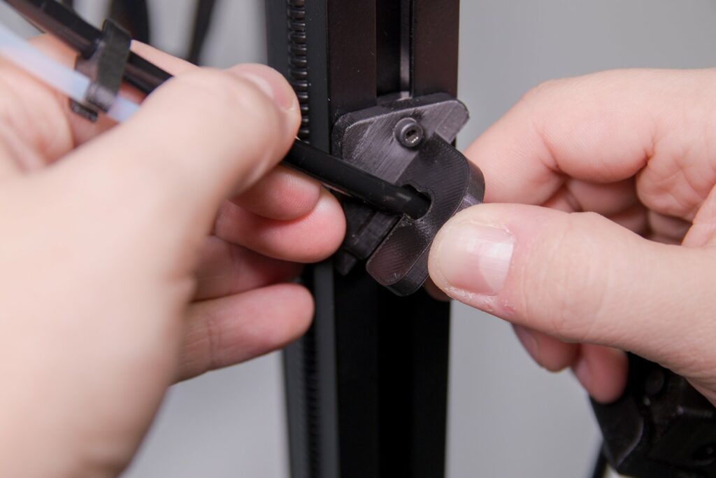
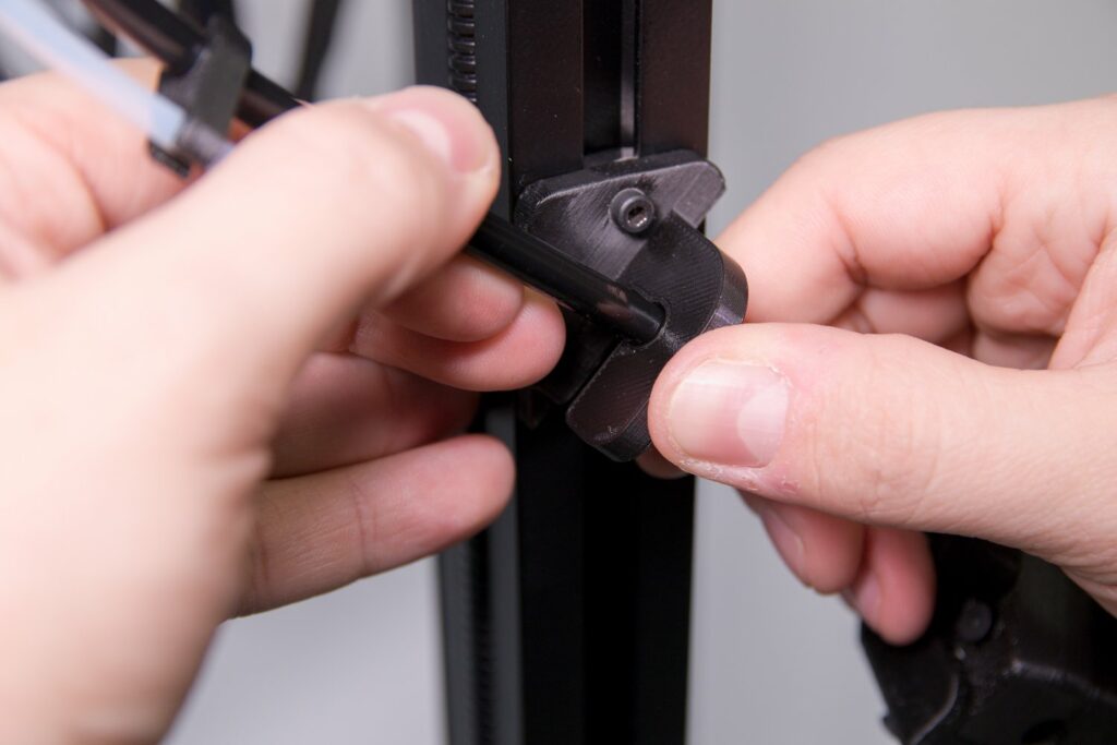
First, remove the three belt locks (the arrows are orange in the shape of an arrow with a notch).
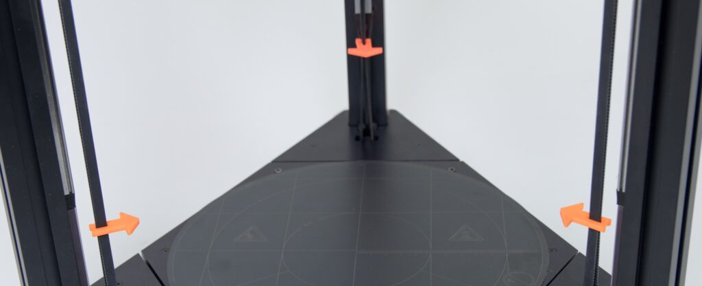
Hold the locking element with the arrow with one hand, hold the belt in its neutral position with the other hand and gently pull the locking element (the arrow) in the direction of the arrow.

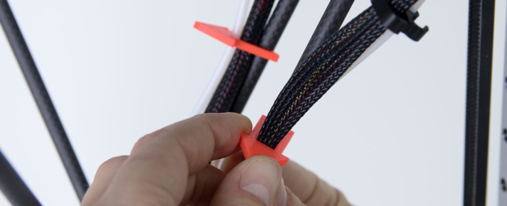
Then loosen the cable and the routing on the printer arms, the same way.

Remove the two protection pieces (arrows) the same way. Hold the printer arm with one hand and slowly remove the pieces in the direction of the arrows.


5) Filament holder location
This part is easy. Place the filament holder on the rear vertical profile of the printer.

Orient the filament holder according to the following photos of the printed counterpart on the printer profile.

Using your thumb to check that the filament holder is properly fitted in the counterpart. The top edges should be aligned.
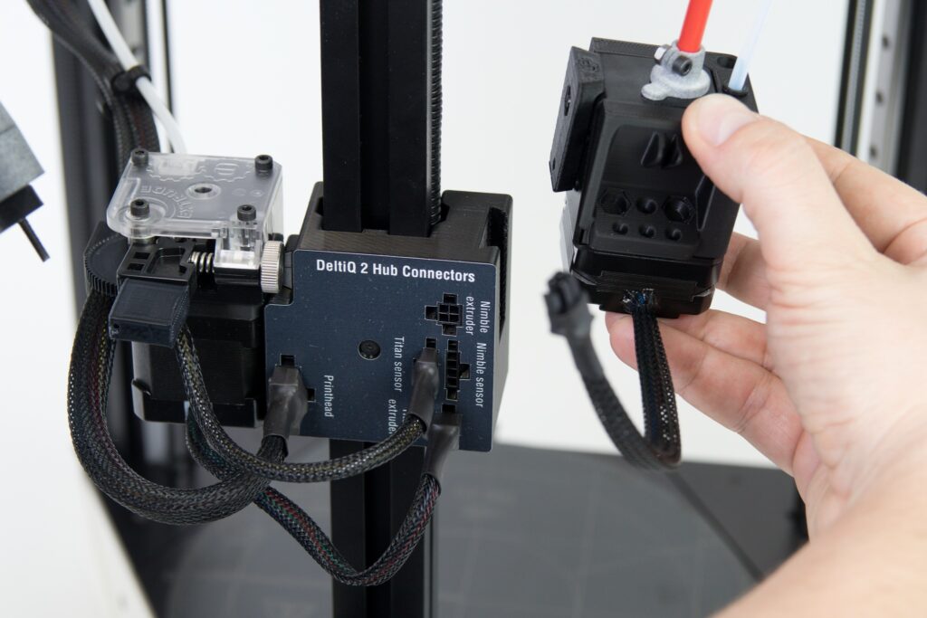
6) Connecting the E3D Titan Extruder
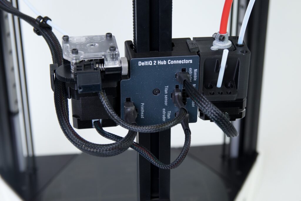
The entire purpose regarding this section of the manual is to connect the Titan extruder to the printer hub on the rear vertical profile.
As a part of constant development, the appearance of the hub has changed. This is what it looked like until October 2020 and you can still come across this model.
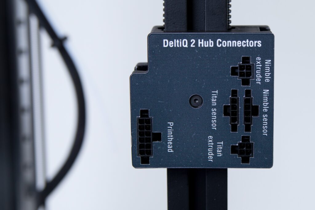
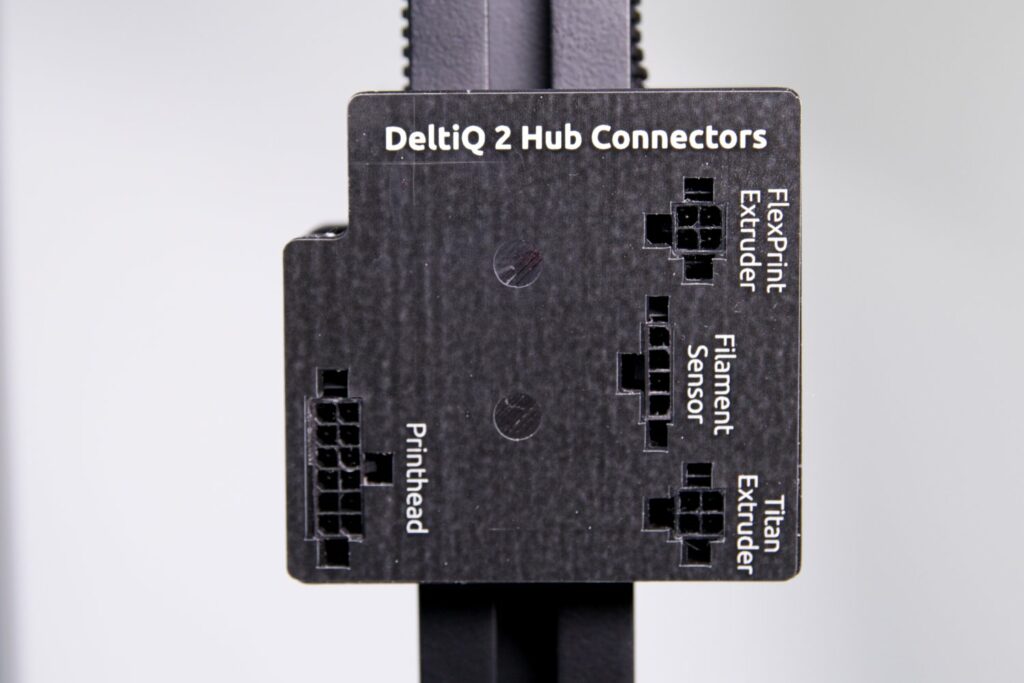
Printers manufactured from November 2020 onwards already have a hub with the design shown in the picture below, but the connectors and wiring system are the same, so the older hub image will be shown in the following steps.
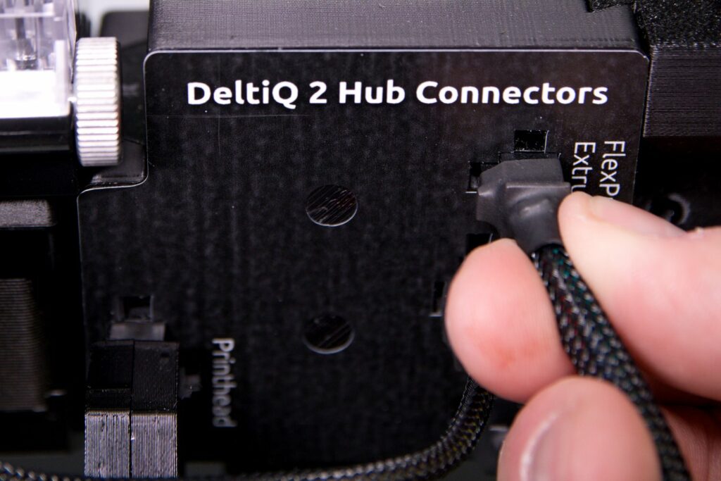
A new version of the extruder for printing flexible materials has been available since November 2020 – FlexPrint 2. Since the previous version, the Nimble extruder is a part of the FlexPrint series, the markings at the hub connector socket have been unified.
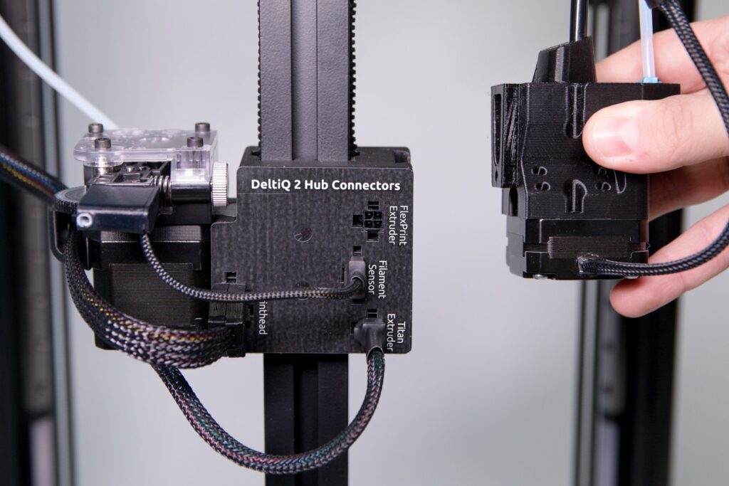
Remove the Titan extruder from the accessory box and place it next to the hub as shown.
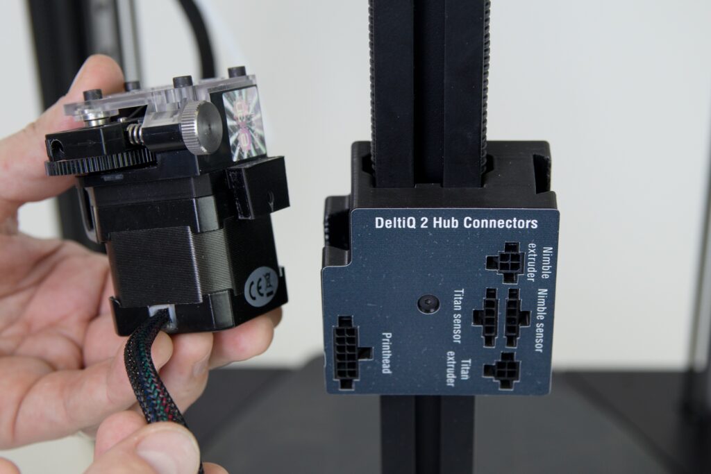
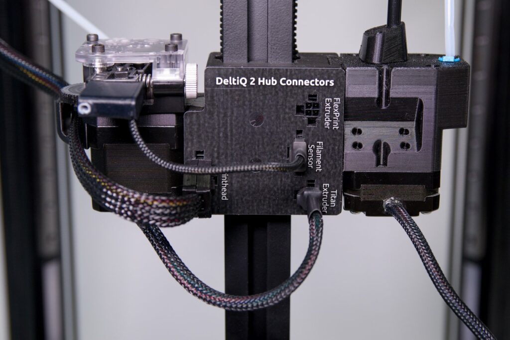
Then insert the extruder into the corresponding recess in the hub. Gently push the extruder into the hub.

From the side of the printer, check that the extruder is fitted flush on the hub. The bottom edges of the extruder and hub must be aligned.

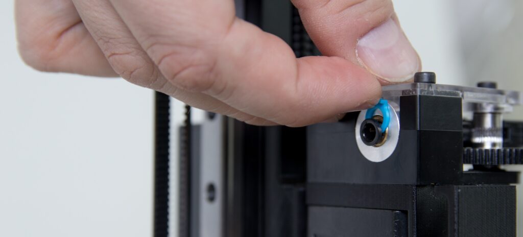
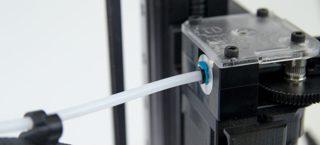
The extruder comes with a blue safety collar around the bowden grip. You must remove it before you can continue with the next step. To do this, simply pull the collar by the extended part.
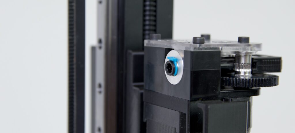
Caution: Keep the blue safety in a safe place as you’ll need it later
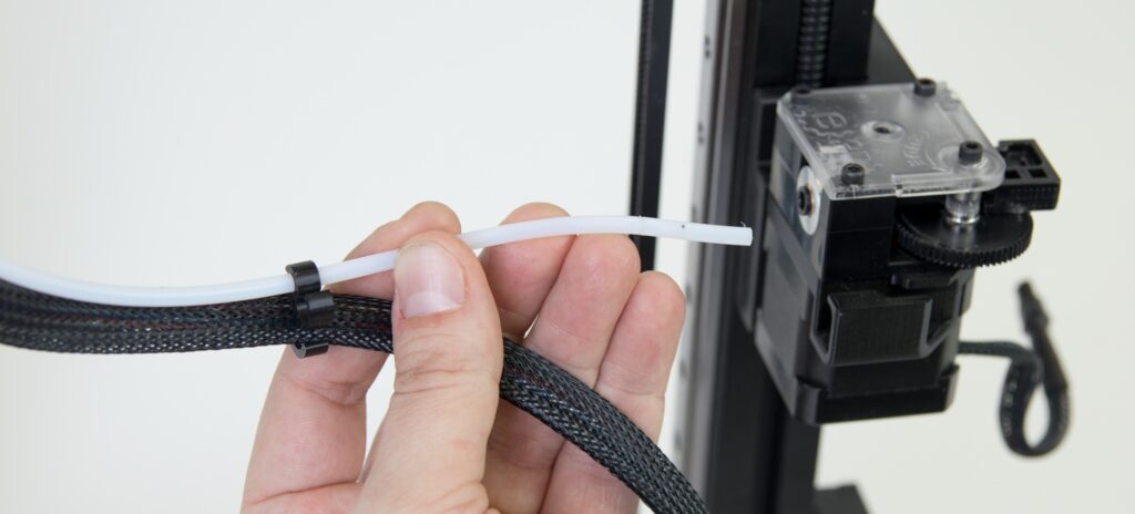
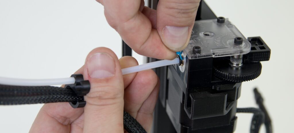
Now insert the filament bowden cable into the extruder.

After the guide has reached the extruder, pull out the Bowden cable slightly to ensure that the Bowden cable has no slack. Put the blue collar back into its place.

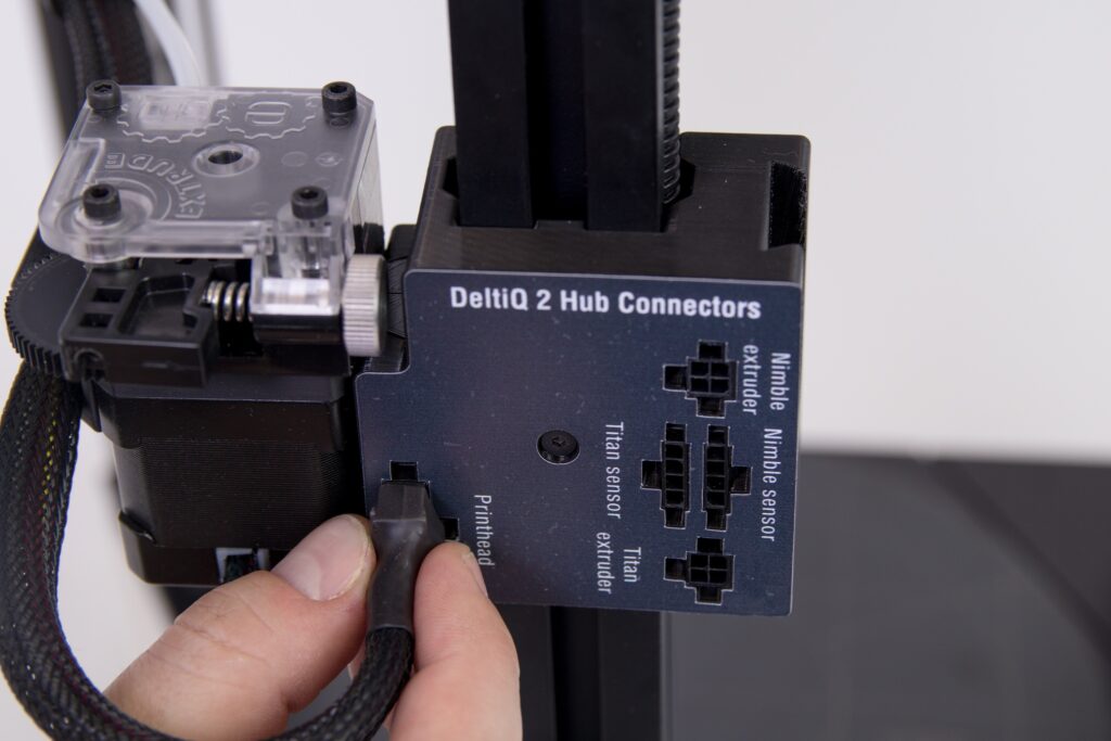
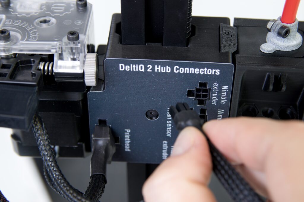
Next, attach the print head wiring harness to the hub. The first step is to secure the wiring harness onto the grip of the extruder.
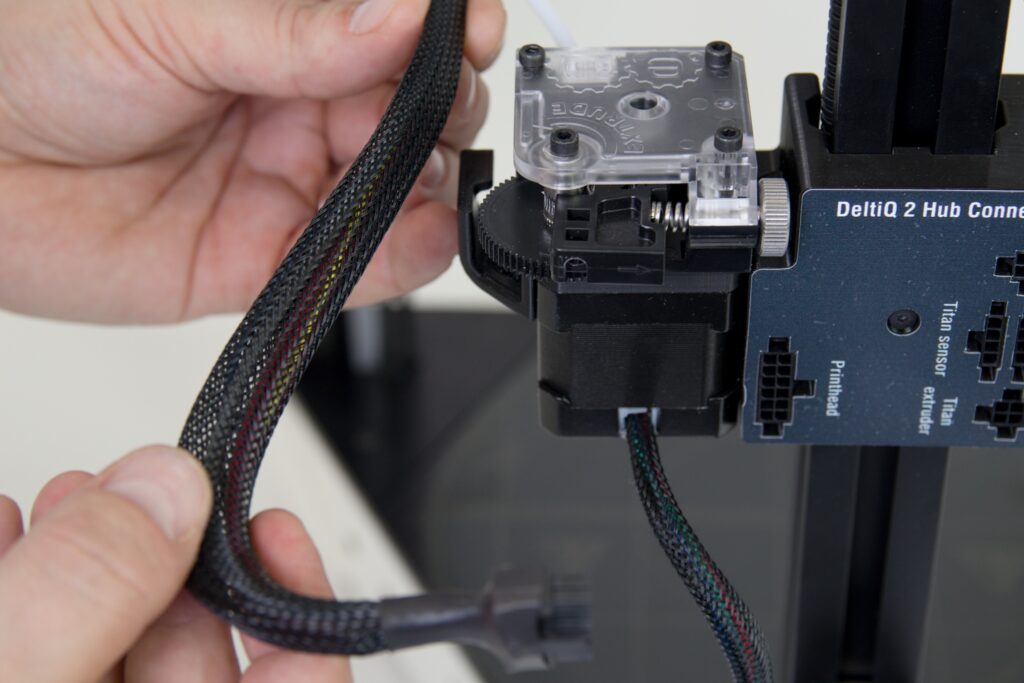
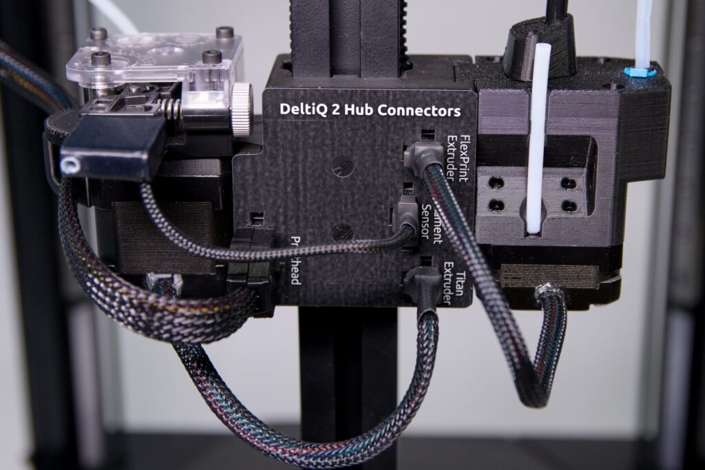
After attaching the wiring harness, plug the connector into the jack labeled Printhead.
Caution: You must hear or feel an obvious click when you plug all hub connectors. This is the only way to make sure that everything is properly connected.
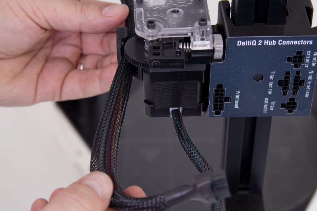
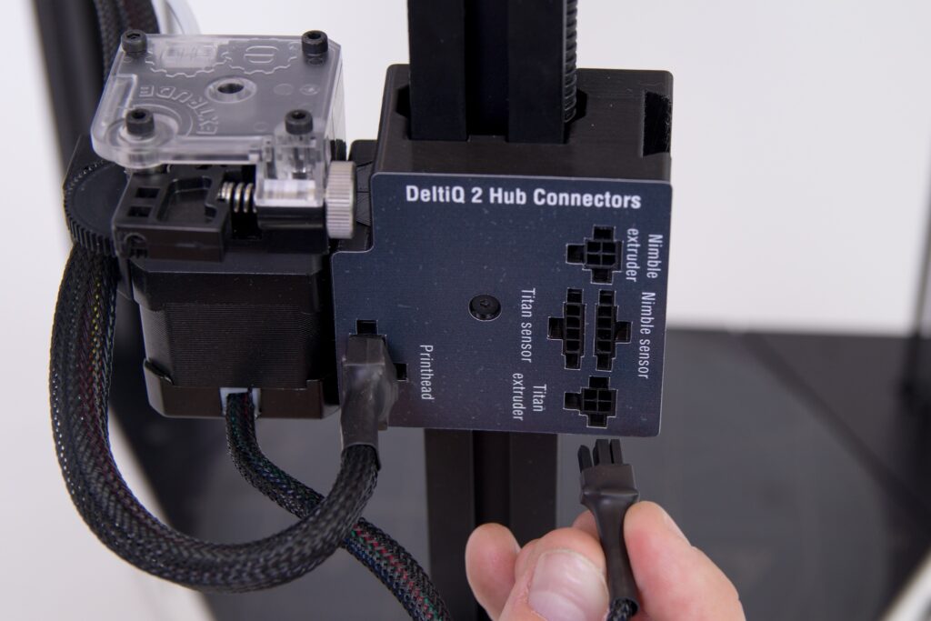
Plug the short cable coming out of the extruder into the socket labeled Titan extruder.
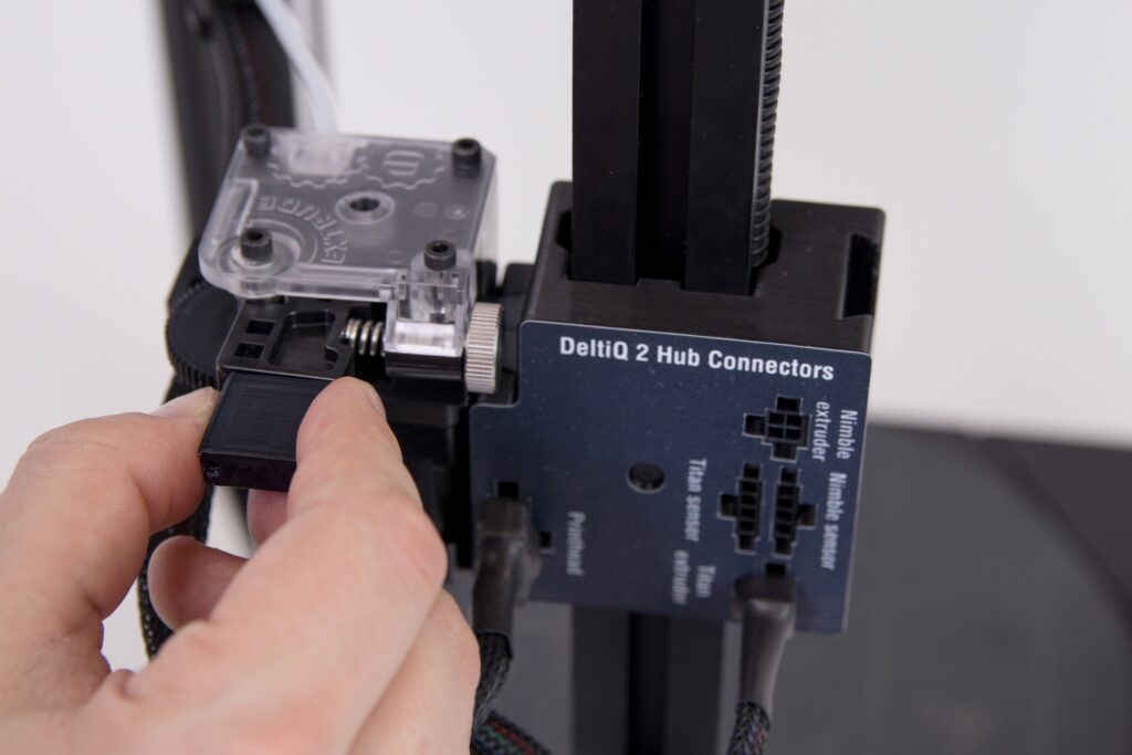
Remove the short-cable filament sensor from the accessory box. Insert the filament sensor into the inlet port of the filament extruder as shown in the following figures.

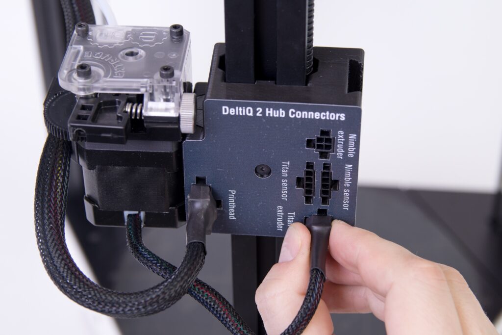
Then plug the connector of the filament sensor cable into the Titan sensor socket. In the new type of hub, connect the connector to the Filament Sensor socket.
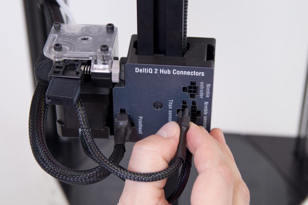

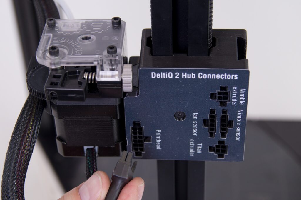
Carefully check the cable connections as shown below.
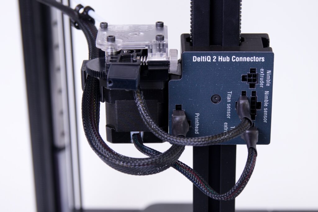
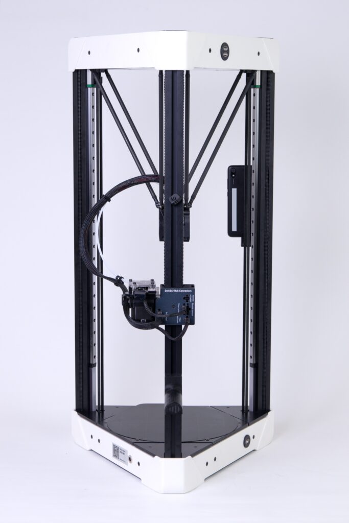
This completes the installation of the Titan extruder to the printer hub.
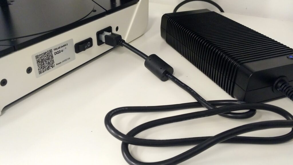
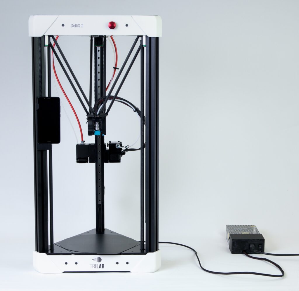
7) Connecting the power supply
Caution: For EU customers, we supply a 240 V source by default. Please check if the source is 240 V or 110 V when unpacking. Switching between these is done on the side of the power supply.
Caution: Since the April 2021, printers have been delivered with different power supply however the connection system is very similar. The part describing the new power supply is located at the end of this section.
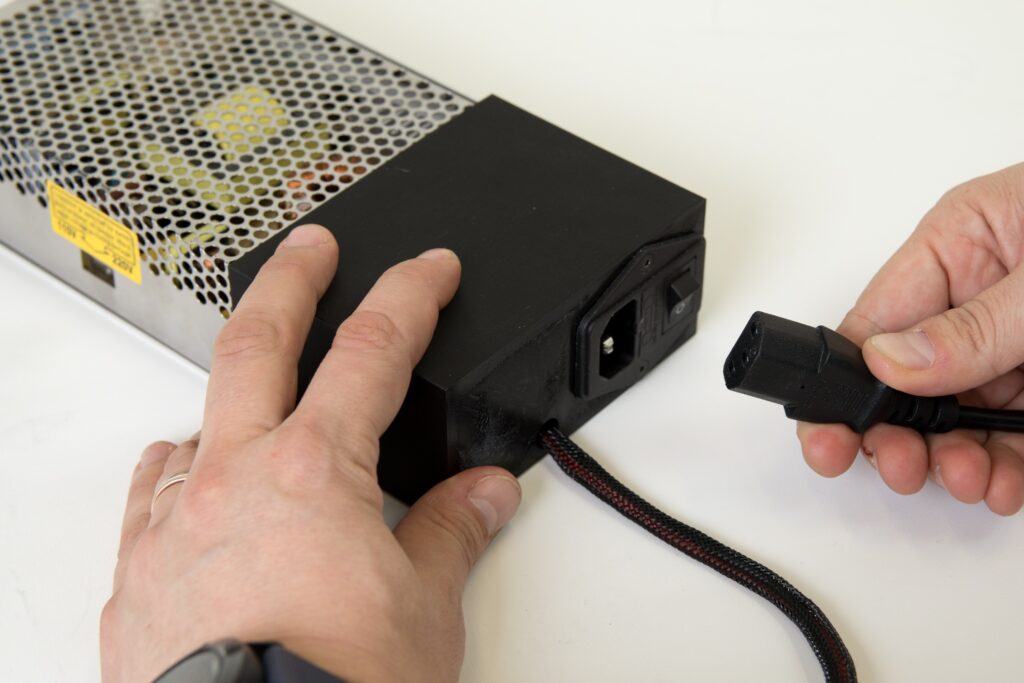
Before connecting the power cord, make sure that the power supply is turned off (rocker switch in the wheel position).
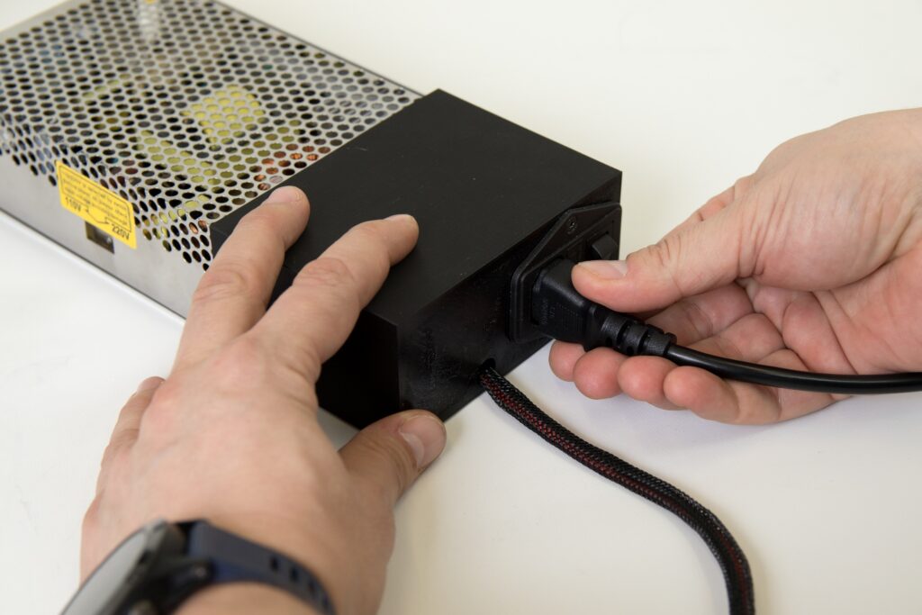
Connect a three-wire power cable to the power supply. The cable must be connected firmly and there must be no sign of play after connection.
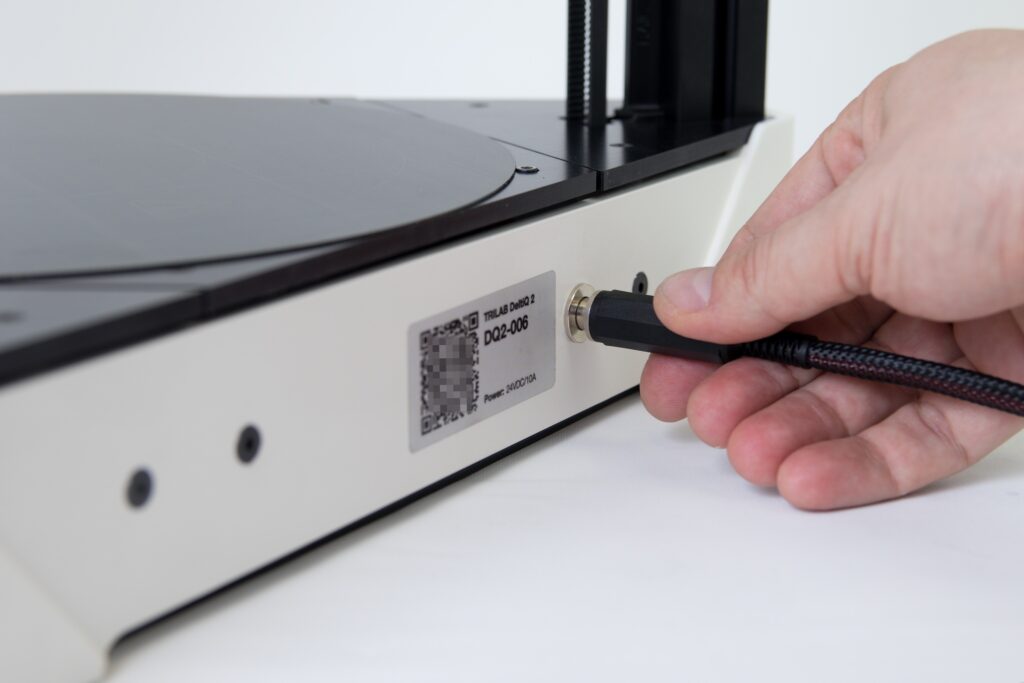
Then connect the second cable from the power supply to the printer.
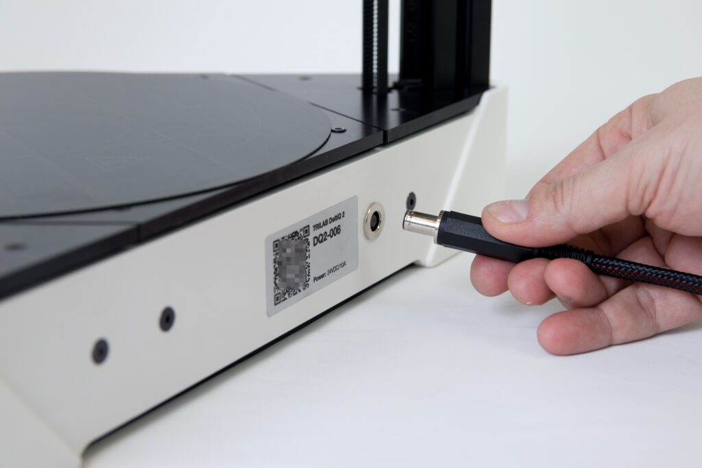
The DC connector must overcome two points in the socket itself when connecting, so you will hear two “clicks”. The design of the connector causes the connector to seem as if it were not fully plugged in even after a successful connection. This is a normal connection, please reference the following photo.
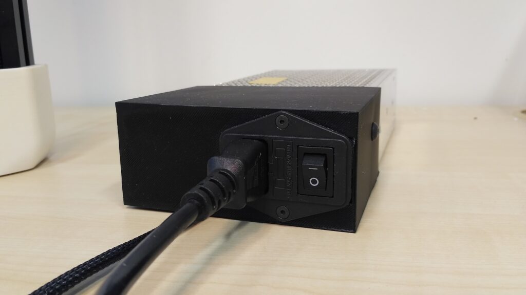
If you have the new power supply, the rocker switch is located on the right bottom side between the QR code and the socket.
Before connecting the power cord, make sure that the power supply is turned off (rocker switch in the wheel position).
This was the last step in installing the single extruder printer. If a second extruder is not supplied with your printer, you can now start the printer. If your delivery includes the TRILAB Flexprint extension, proceed to the next chapter.
Carefully check all of the connections, turn on the DeltaControl display by holding the button on the side of it, and turn on the printer with the rocker switch.

Installing the TRILAB Flexprint extension
If you ordered a printer with the TRILAB Flexprint extension, you will find another modified extruder in the box.
Remove the mounted Nimble extruder from the accessory box and prepare it as the image shows below.
Place the extruder in the slot of the hub and gently push the extruder into position from above until it is fully & firmly fitted in the hub

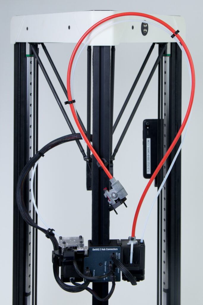
Curl the other end of the extruder as shown in the following figure, and then snap the red cable onto the bracket located on the rear vertical profile of the printer.
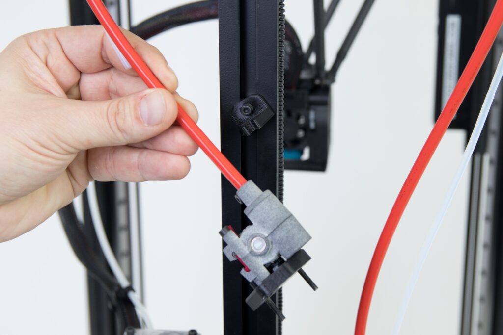

Snap the extruder cable into the hub into the socket marked “Nimble extruder” as shown in the figure.

You will also find a short Teflon tube in the accessories, place it into the holder at the back of the extruder.

Tip: You’ll find another PTFE tube in the accessories. The second is an added bonus by us just in case you lose the first.
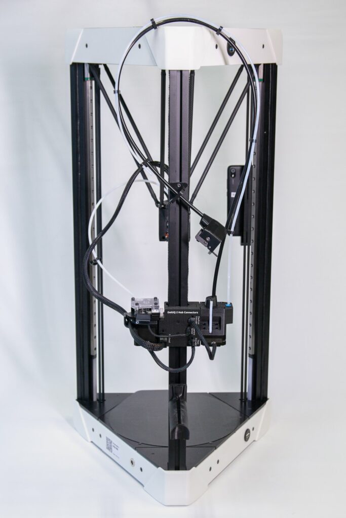
This completes the hardware installation of the TRILAB FlexPrint extension.
Carefully check all of the connections, turn on the display by holding the button on the side of the DeltaControl, and start the printer with the rocker switch on the power supply.
Installing the Trilab FlexPrint 2 extension
This extruder is installed and operated very similarly to the previous model.
To mount the new FlexPrint extruder, you must first screw bracket onto the rear vertical profile.
Prepare the holder with the tightening nut so that a part of the nut protrudes above the holder.
Place the bracket, in the same orientation as in the picture, in the vertical profile so that its screw is 20 cm above the connector hub.
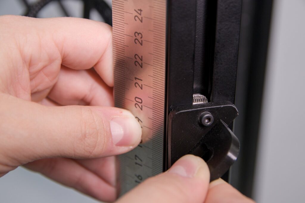
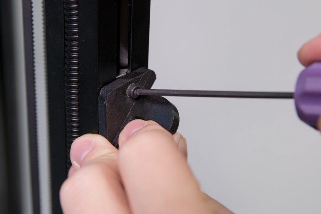
And tighten with the supplied Allen key.
Remove the FlexPrint extruder with assembly from the accessory box and prepare it in the orientation shown in the following figure.
Place the extruder in the notch of the hub and slowly push the extruder into position from above until it is fully seated and firmly fixed in the hub.
Twist the other end of the extruder as shown below, and then snap the black cable into the bracket located on the rear vertical profile of the printer.
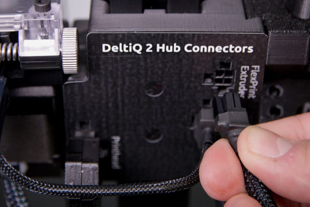
Snap the extruder cable into the hub at the location marked FlexPrint Extruder in the orientation indicated by the image.
T
he accessories also include a short PTFE tube, which you place in the holder at the back of the extruder.
Tip: You will find several spare parts in the accessories, including a Teflon tube. The second is an added bonus replacement by us just in case you lose the first.
After completing this step, the hardware installation of the TRILAB FlexPrint 2 extension is complete. If you install the extension yourself, you still need to activate this component in the printer interface as the last step.
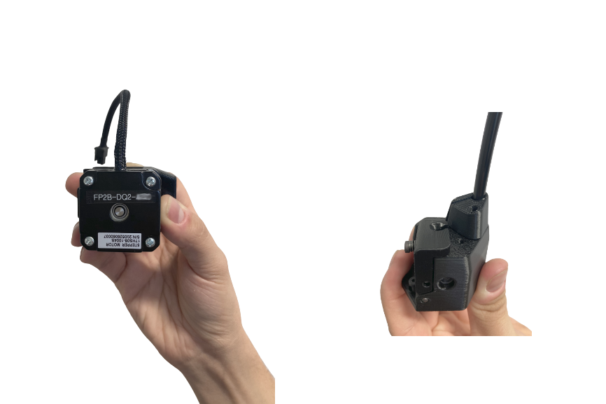
Since the April 2021 there has been slightly modified version TRILAB FlexPrint 2B. This version differs by two details as you can see below. On the bottom of the engine part there is serial number in the form FP2B-DQ2-XXX. In the printhead part there is only a little screw hole to prevent loss of the screw.
Depending of the FlexPrint verison,it is necessary to activate this extension using corresponding configuration file.
For the version TRILAB FlexPrint 2 download this file flexprint2-config.gcode.
For the version TRILAB FlexPrint 2B download this file flexprint2b-config.gcode.
Upload the file to the printer and run it as a normal print job. After launching, you will see a message within 2 seconds about the successful setup of the extension. You can then delete the file from the printer again.
If the placement of the FlexPrint Extruder gets in your way while not in use etc., you can unplug it when the printer is turned off. Just follow the steps to install it in reverse order.
Caution: Frequent handling of the connectors can reduce their functionality and therefore we recommend to minimize all handling.
Adjusting the first layer height
Before your first print, you’ll need to set the correct height of the first layer respecting the distance between the nozzle and pad. We recommend not to underestimate this setting, a good first layer has a massive effect on the adhesion to the pad and the entire print of each model.
Caution: Each material behaves slightly differently when printed, and the previous settings may need to be adjusted when changing media.
Tip: Before adjusting first layer height, we recommend to watch this instructional video.
To set the height of the first layer, we recommend using the PLA material and the simple model DQ2_50x50mm_plate.gcode prepared by us from the Demoprints folder.
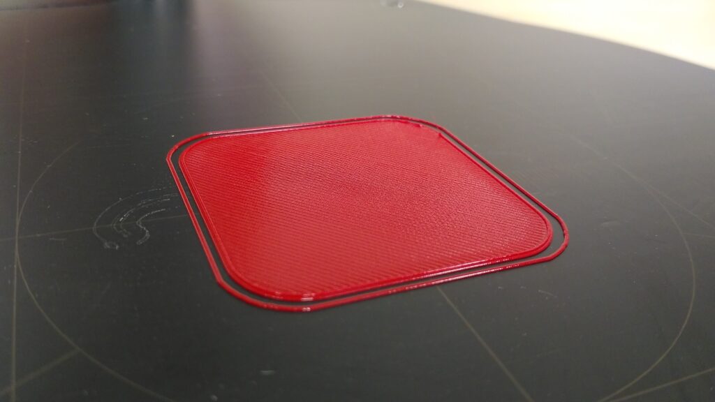
A well-adjusted first layer is smooth to the touch, looks uniform, has no gaps between the circumferential walls and the inner filling, and the individual fibers hold together even when bent.
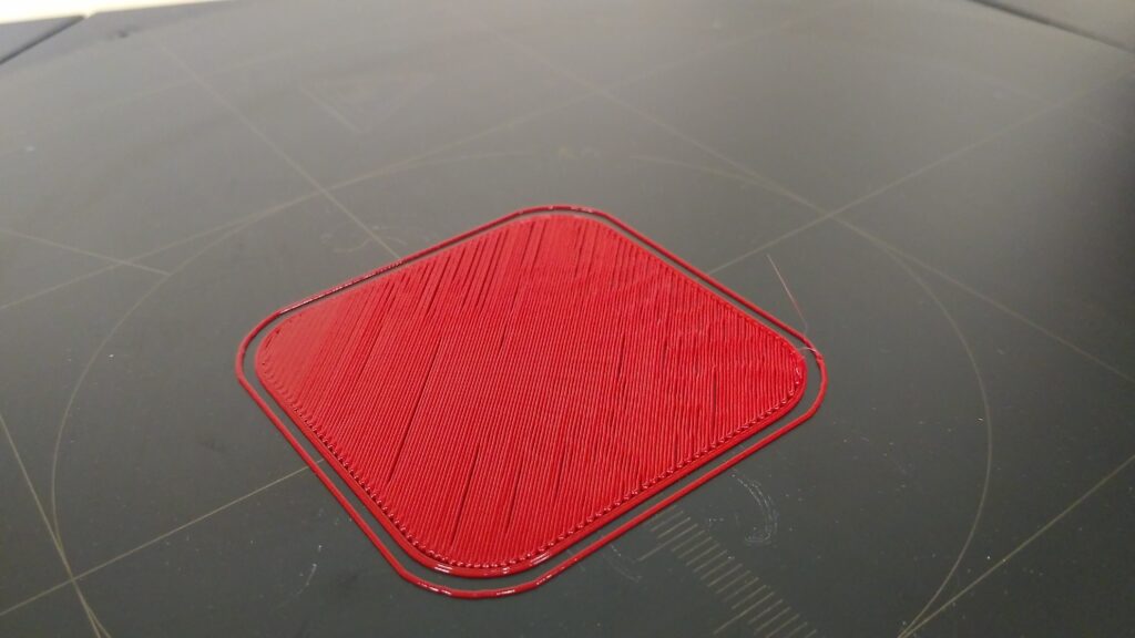
A layer that is too low has scratches caused by the movement of the nozzle and these scratches can be felt by touch. If this situation occurs, increase the Z-offset value using, for example, the +0.05 mm button, in the DeltaControl application on the Tune tab.
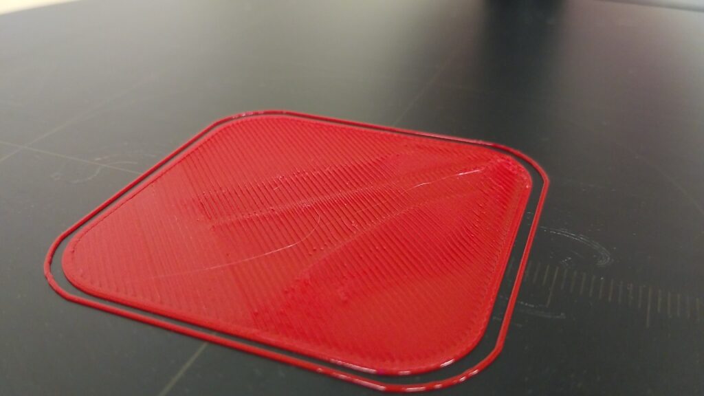
The opposite extreme, a first layer that’s too high, is manifested by gaps between the circumferential walls and the inner filling, poor adhesion to the pad and gaps between the individual fibers may also occur. If this situation occurs, decrease the Z-offset value using, for example, the -0.05 mm button, in the DeltaControl application on the Tune tab.
Warning: During the lowering process, be very careful not to lower the Z-offset too much and, in extreme cases, cause the nozzle to hit the pad.