
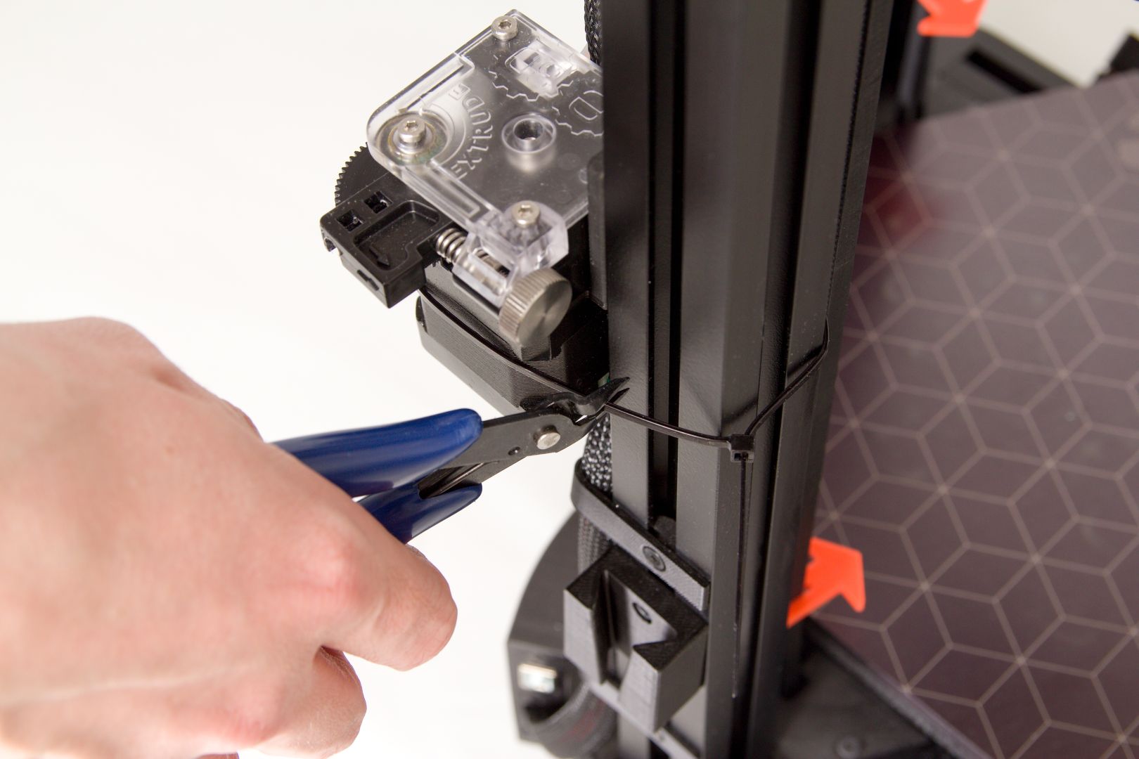
Remove the zip-ties fixing the Titan extruder
Using the supplied wire cutters, cut through the fastening tape around the extruder. You will no longer need this tape; you can throw it away.
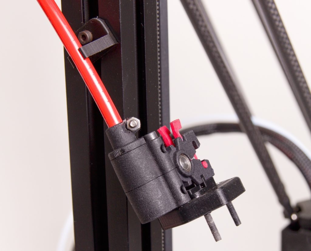
Remove the zip-ties fixing the Nimble extruder and the DriveCable
If your printer is equipped with this optional acessory, please remove the securing zip-ties and park the extruder in the prepared parking mount.
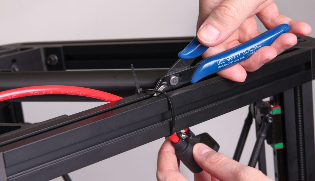
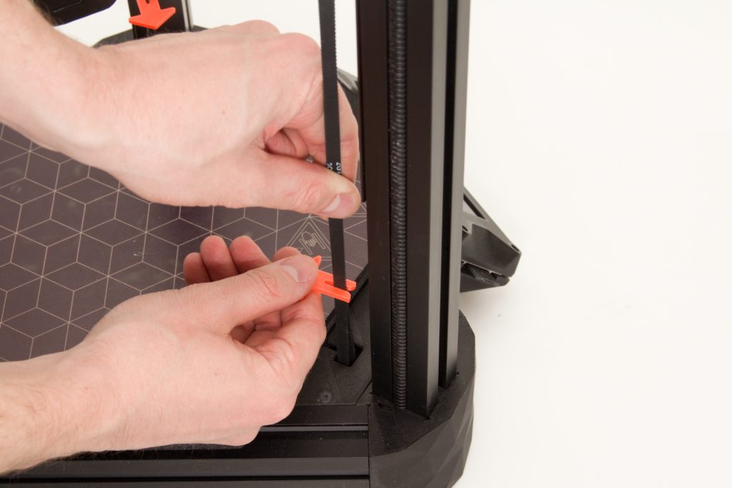
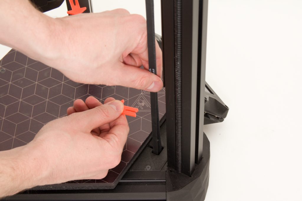
Remove the Drive Belt Fasteners
Remove the clamps fixing the belts. Do not throw out the 3 fasteners that you have released this way, as they will be useful if you later transport or move the printer.
Warning – moving the machine without these fasteners can cause the belts’ motion to be transferred to the motor and thereby damage the printer’s electronics!
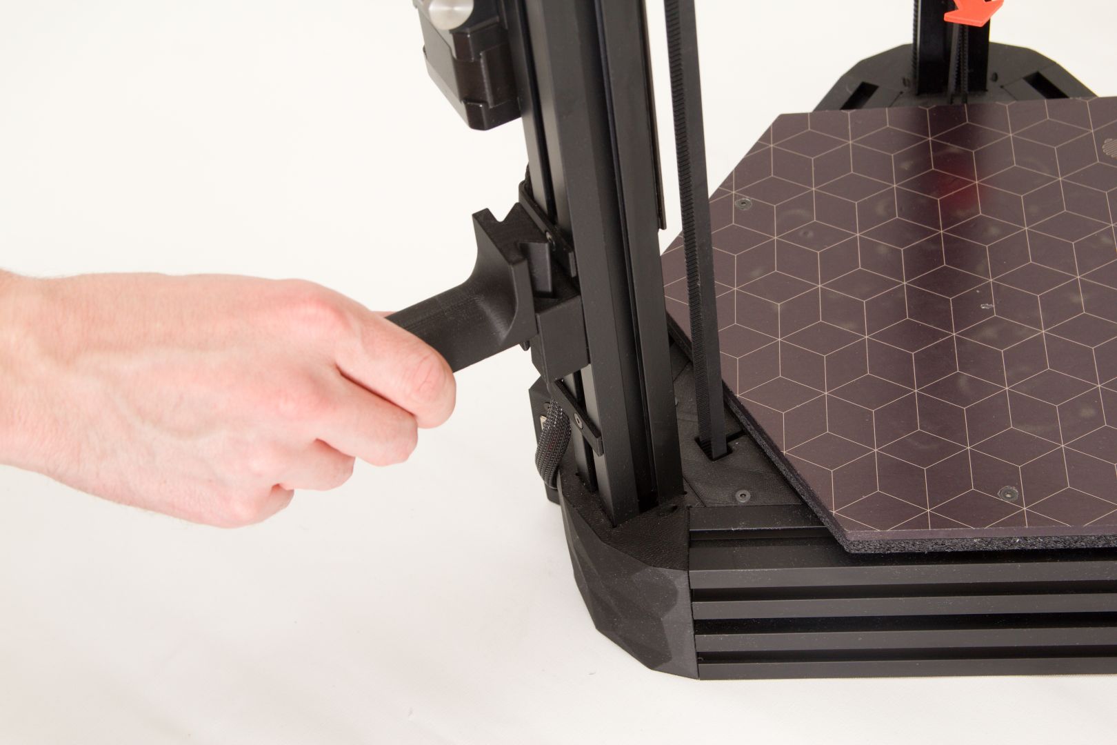
Attach the Filament Holder
Snap the universal filament holder into the component prepared for this purpose in the rear section of the printer.
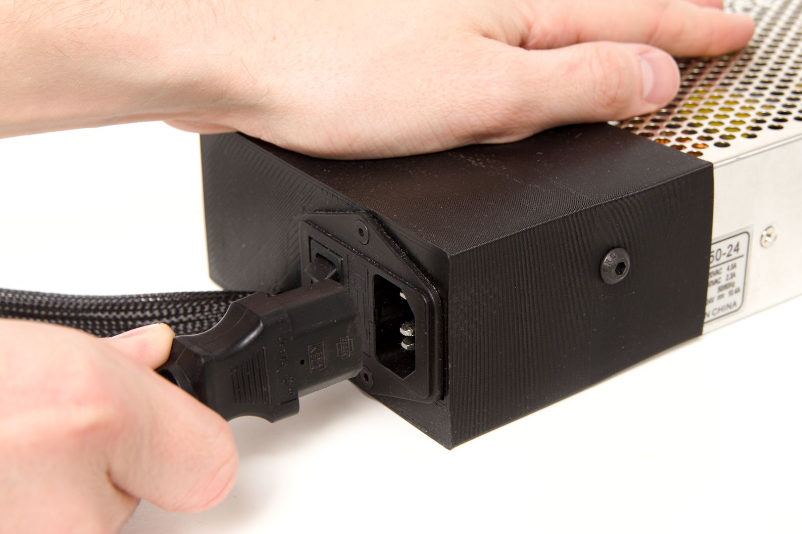
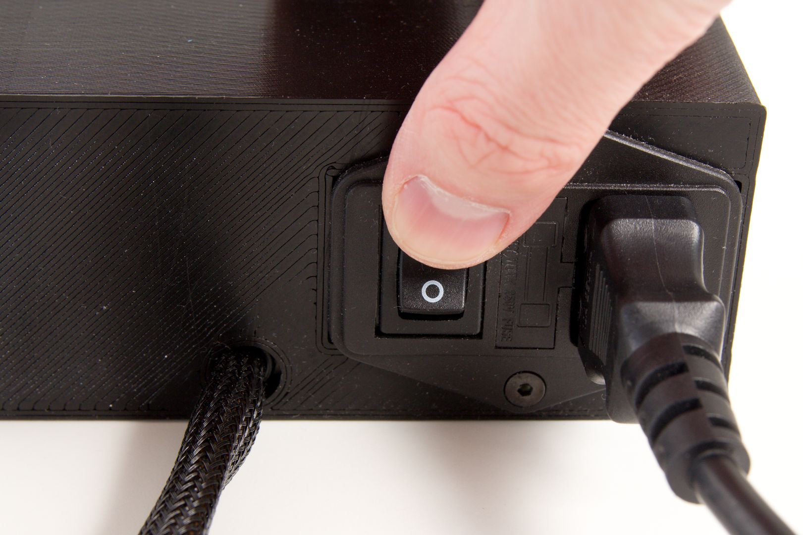
Connect the Power Supply Cable
The supply is furnished with a standard Euro connector. Before plugging it in, make sure that the cradle switch is in the off (O) position. Hold the power supply in your left hand and use your right hand to push the connector into the supply in the marked orientation. The connector must hold fast in the supply, and there must be no risk that it will fall out during normal handling.
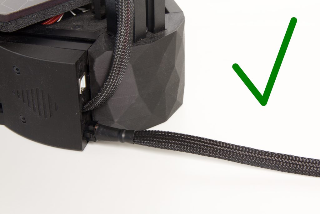
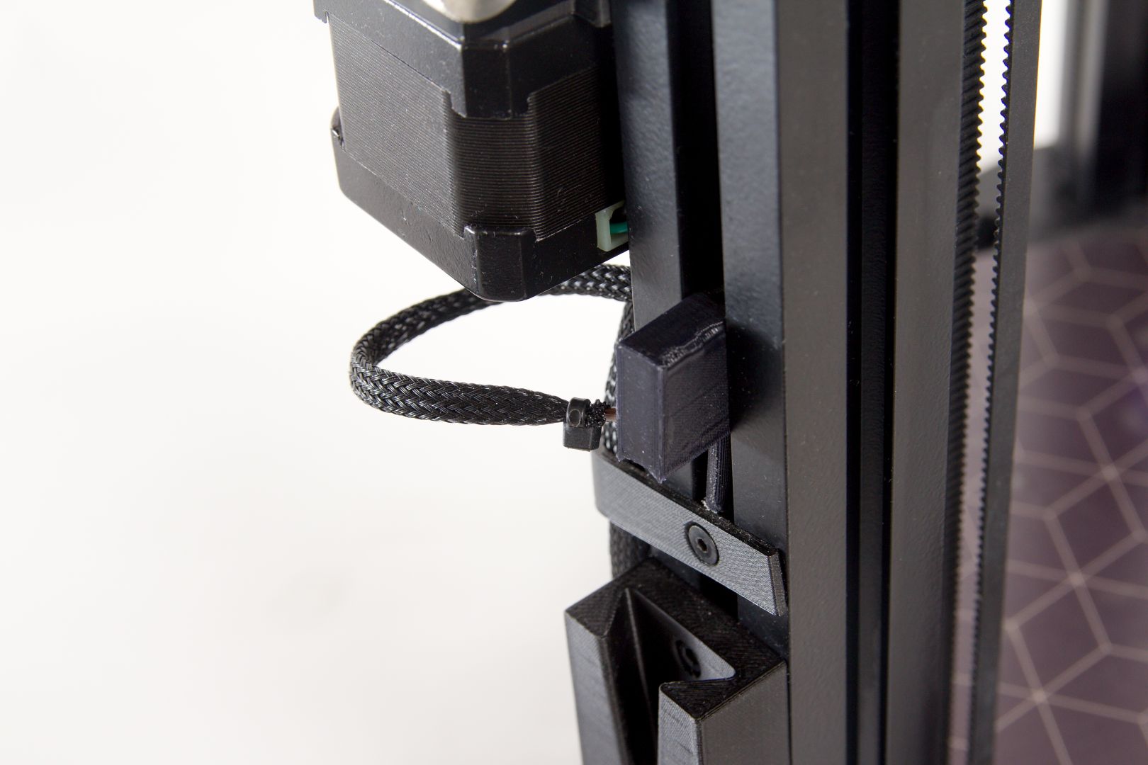
Connect the Power Supply to the Printer
Connect the cable from the power supply into the panel that is next to the printer’s rear section (column). Orient the cable as per the photo below (with its “beak” facing out of the printer). The beak will snap into the catch to indicate that the cable has been inserted sufficiently and correctly.
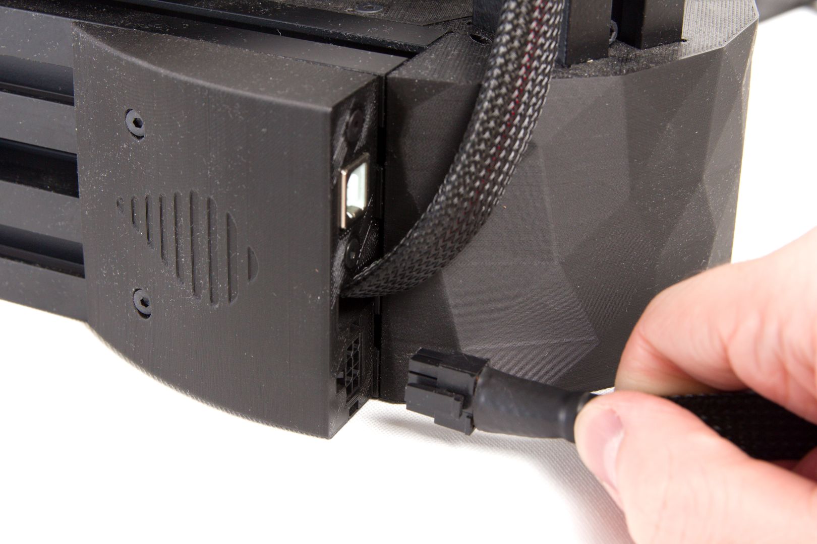
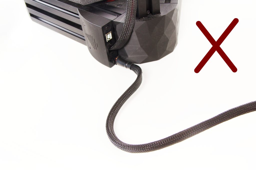
Caution: It is important that the cable from the printer not be bent, folded, or otherwise deformed.
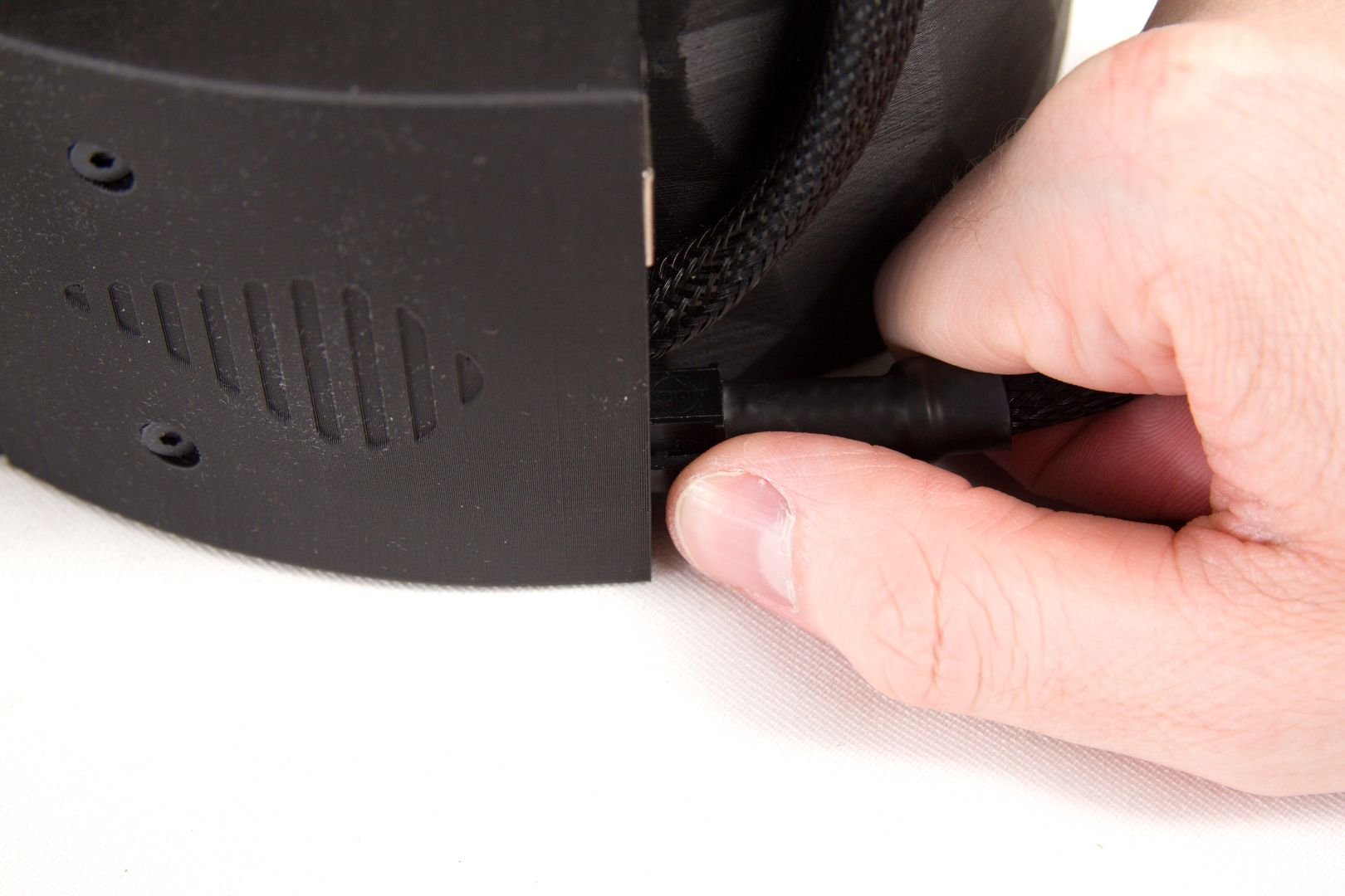
How to Disconnect the Power Cable
Before transporting the printer, disconnect the power supply from it. Press in on the beak by the place where the cable is connected to the printer, and pull out the connector. Do not bend the cable.
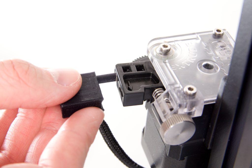
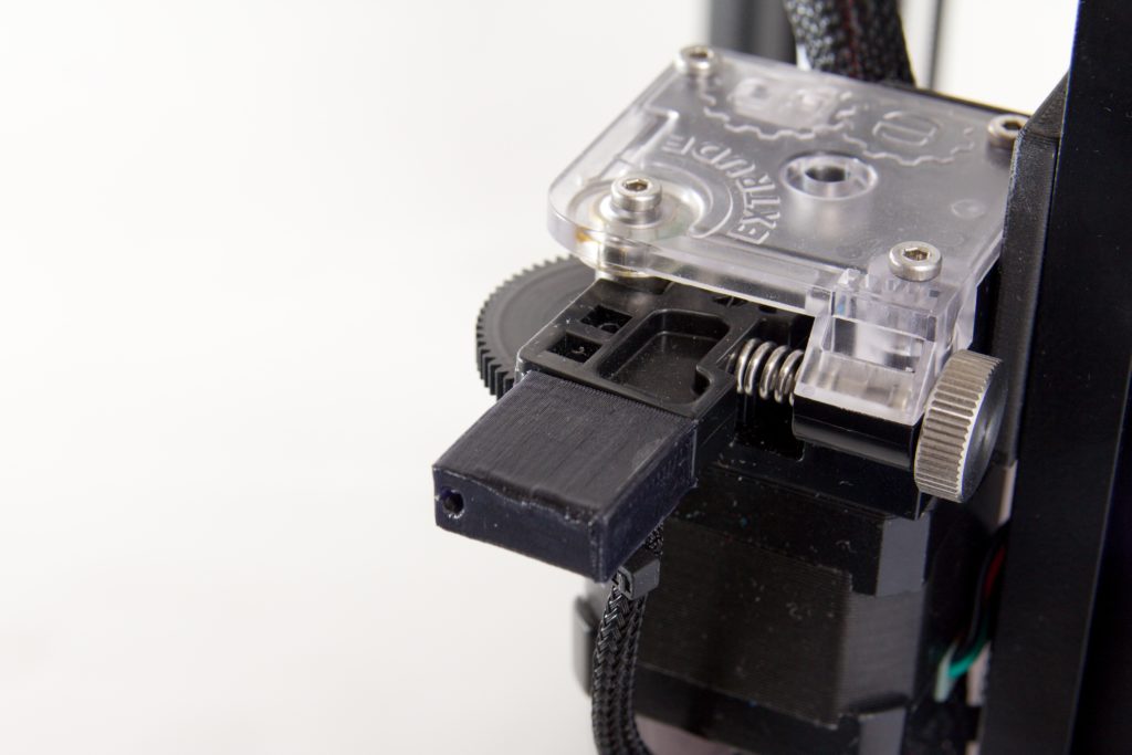
Connecting the Filament Sensor
The filament sensor monitors whether the filament is still entering the printer and stops the current print job if the reel runs out. The sensor is located inside of a plastic module that is to be placed in the printer’s rear profile (column) under the extruder during transport. Using a bit of force, place the sensor into the filament entry in the extruder as per the pictures below.
When disconnecting it for transport, perform the opposite procedure—pull the sensor out and store it in the printer’s rear section.
Visual Check of Printer Integrity After Transport
After transporting the printer and before starting it up, it is good to visually check that it has not been damaged. Please check that no freely hanging wires are visible on the printer body, none of the cables’ covers are damaged, the extruder is firmly positioned on the rear section (column), the white Bowden cable is firmly positioned at both ends, and neither the support nor the LCD display shows any signs of damage.
Turning the Printer On
To turn the printer on, use the cradle switch on the power supply. Leave this cradle switch freely accessible—you will be using it to turn the printer on and off.
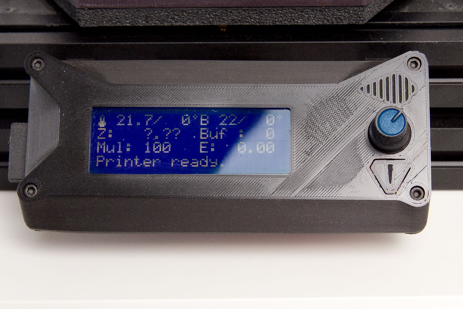
Status check after power up
It is good practice to perform a quick preflight check after power supply power up. Upon startup, the LCD display lights up, followed by a status screen showing current temperatures.
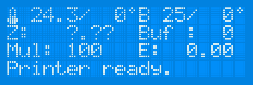
No part of the printer is moving at this moment, nor the printhead neither the printbed are powered and heating. A silent fan humming can be heard from below the printbed.
Printer control
After turning the printer on, first turn your attention to the display as it lights up. This display, the (pressable) control wheel, and the button for resetting the printer form the printer’s control interface.
You can spin the wheel up and down and thereby move around in the menu, set the printer’s temperature, or even manually control the motion of its motors. You can also press it to confirm menu choices or enter submenus.
Use the reset button to restore the printer to its original state at any time.
Warning: Pressing this button interrupts the current print job with no way to go back to it. Pressing this button also stops the heating of the hot end and the base.
Z-axis Calibration
The first step that you must always take directly after transporting the printer is the calibration of its Z axis, that is, its vertical axis. Use these steps:
- Press the LCD panel’s control wheel to enter the main menu.
- Select the Control item and press the wheel again.
- Spin the wheel to reach the Printer Service menu item, and then press it again to select that item.
- Choose “Z home calib”, the printer will respond by moving the printhead to the upmost home position.
- The printer will begin heating the printbed.
- When the base’s temperature reaches 55 °C, the print head will ride down to the middle of the base and then return to its original (“home”) position.
- It will then ride back to the base again, where it will probe the distance to the base at three defined points.
- After this check, the print head will ride back up to the home position.
- After this procedure, the heated base will have a temperature of 55 °C. The printer can be restarted to let the base cool down by pressing the reset button. (The calibration’s result is stored to memory.)
Back: Your new printer
Next: Your first print