
- Introduction – before you start using the printer
- Unpacking and installing the printer
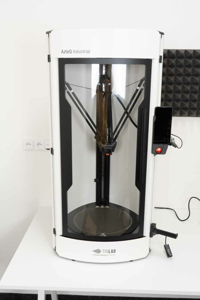
- Getting to know the TRILAB AzteQ printer
- First printing with your AzteQ printer
- Cheat sheat – the usual printing procedure
- How to use the DeltaControl display and application
- How to use the WebControl online interface
- Printer self-installation
- Service tasks on the printer
Subchapters
1) Unpacking…..2) Accessories…..3) Display installation
4) Printhead installation…..5) Spoolholder…..6) Connectors
7) Power supply…..8) First layer
1) Unpacking
Put the box with the printer on the ground, near the final place.
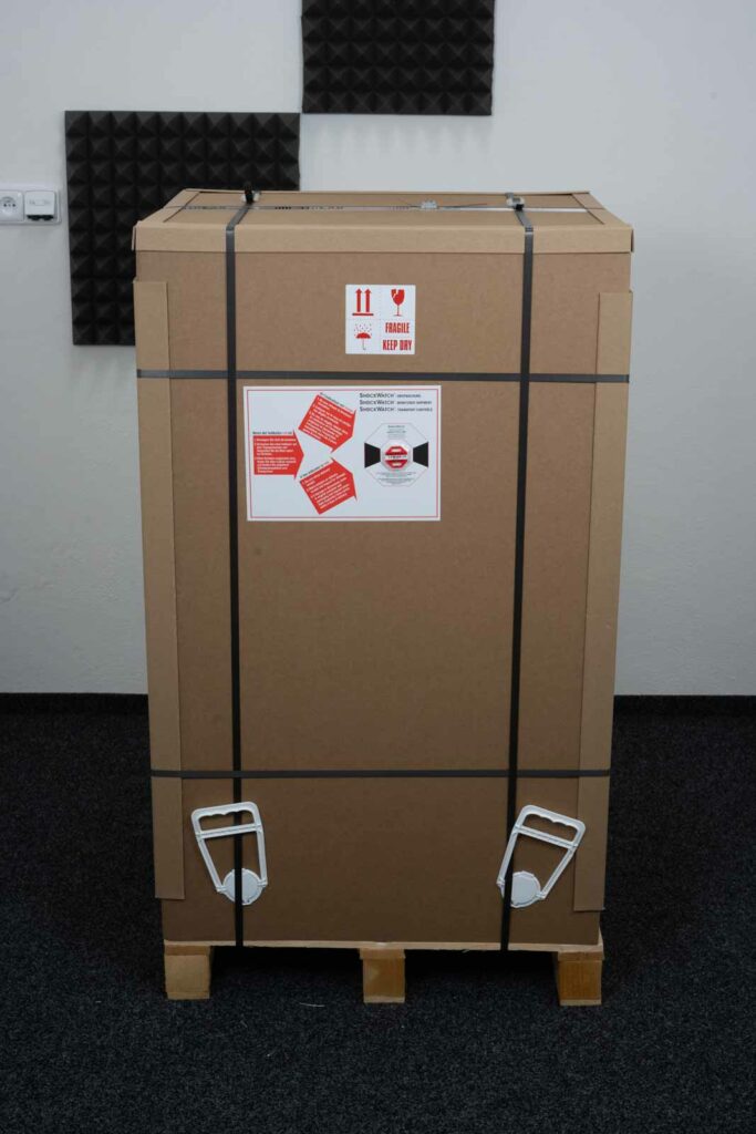
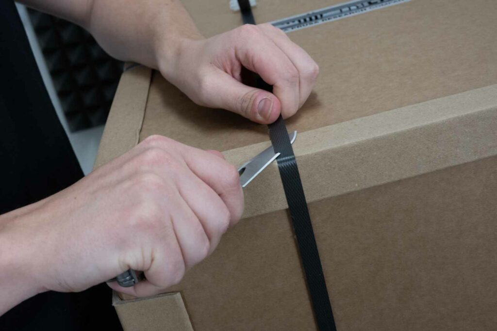
Cut off the plastic wrappers and paper corner protection.
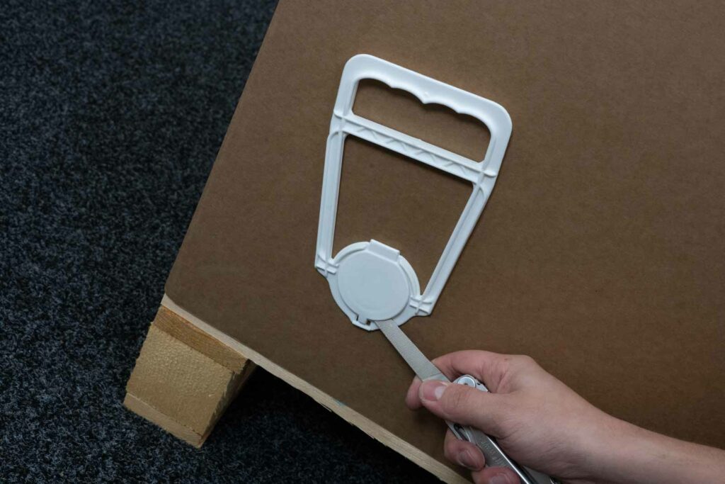
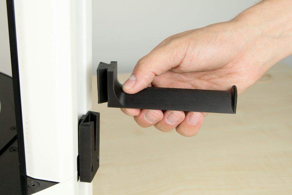
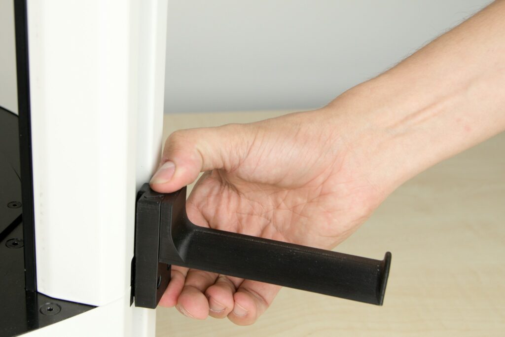
Take out the plastic handles. In their bottom part, there is a clicker that needs to be clicked out.
Tip: It is better to use a flat screwdriver for better access.
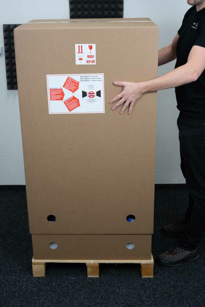
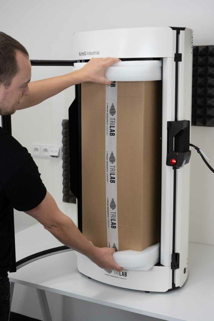
Pull the whole box up.
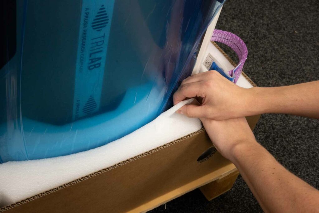
There is a slide-out “lock” in the front of both foam cases. Remove them as in the photos.
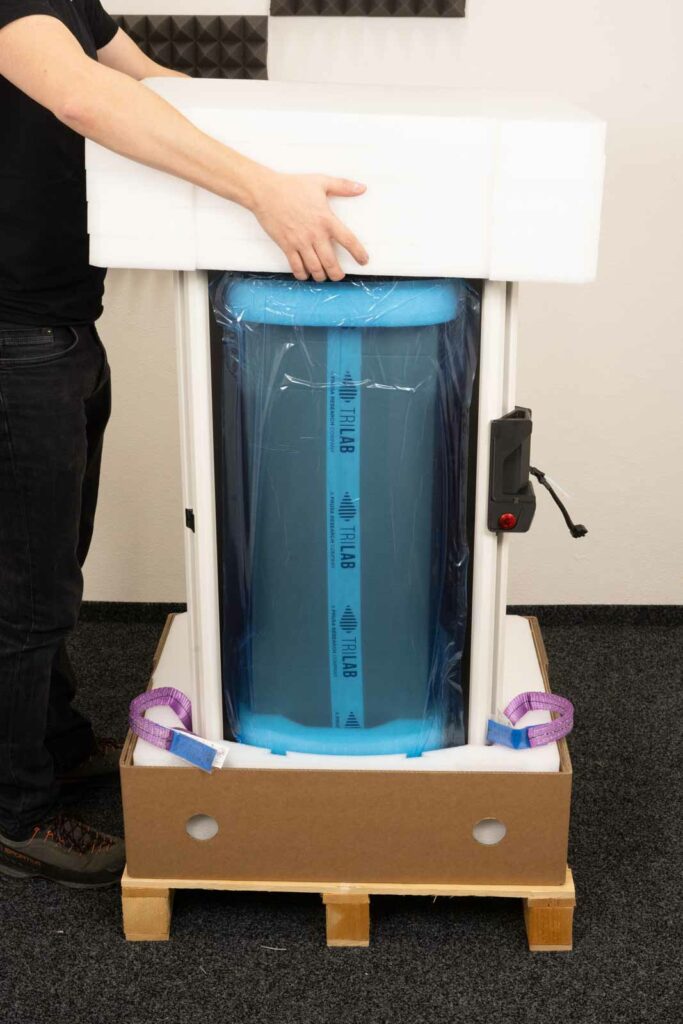
Pull up the upper foam part.
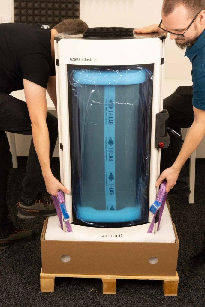
With at least two people, hold the straps in the lower part and control its movement with at least one hand on the upper part of the printer. Stepping on the fiam padding will make it easier to pull the printer out.
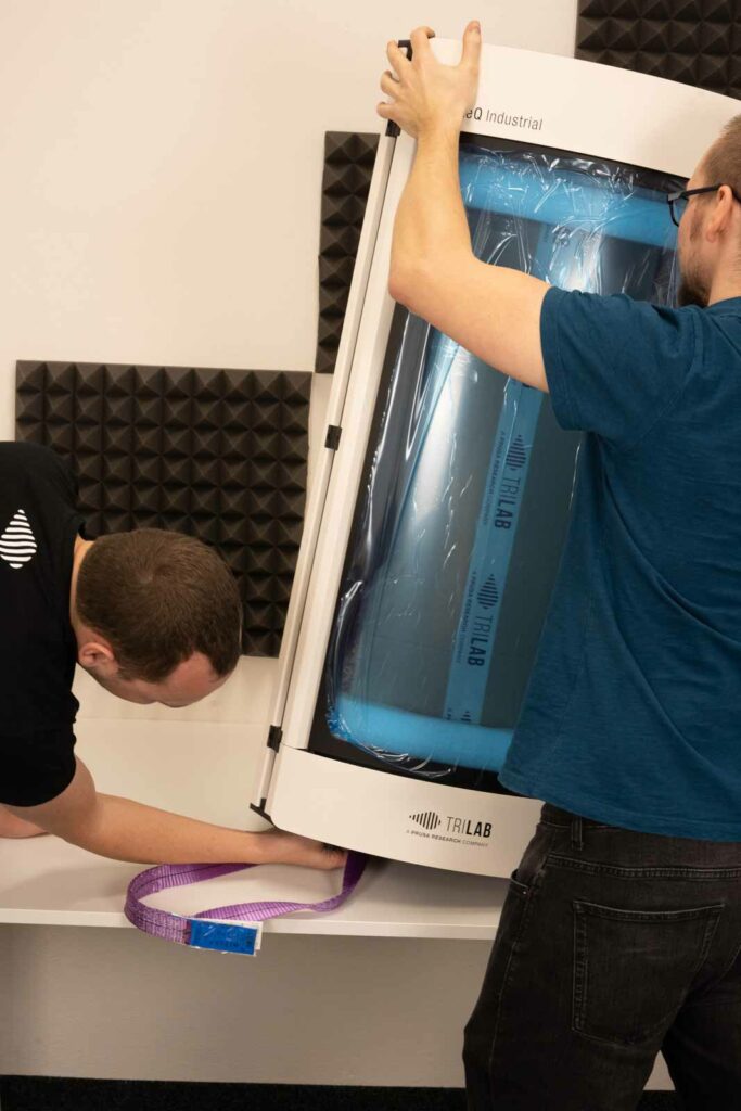
Place the printer on a stable table. To remove the straps you need to tilt the printer slightly and unhook the strap.
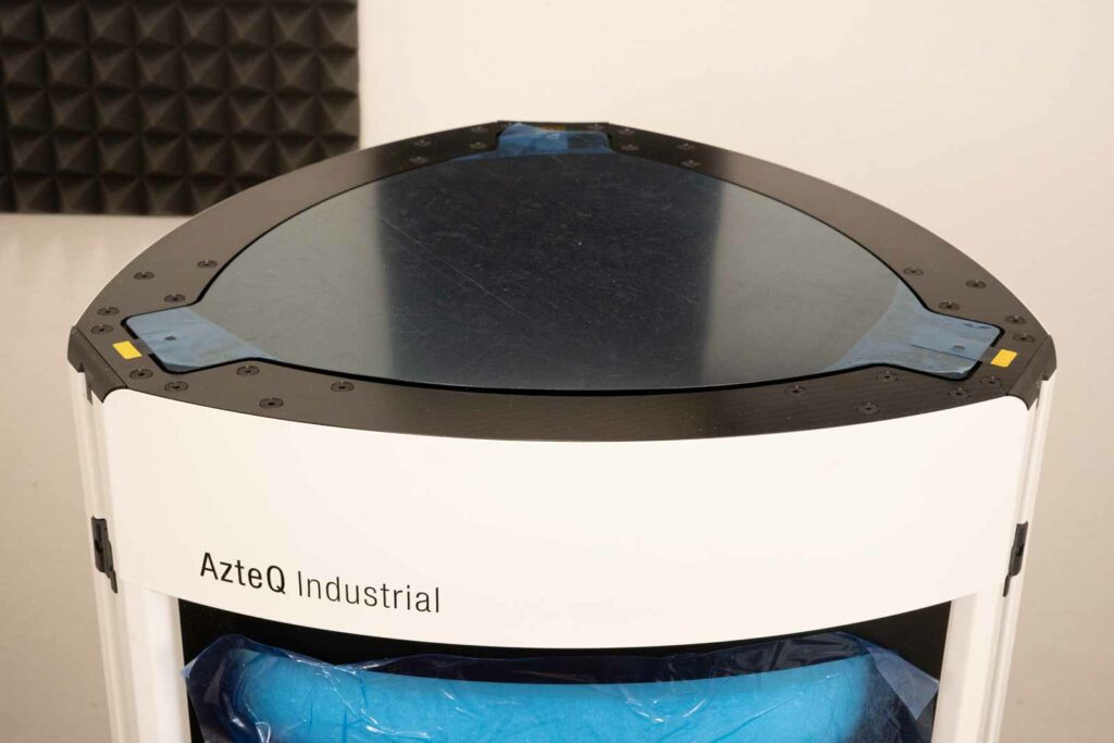
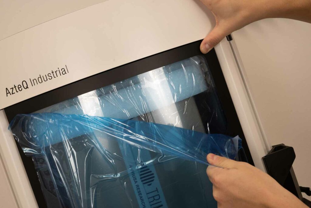
Now remove the protective film from the top cover.
Then from both sodes of the door. Always hold the door lightly, the foil can then be removed more easily.
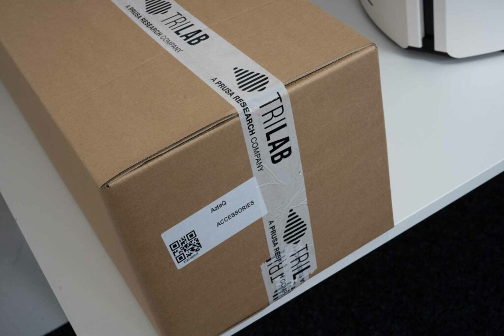
Take out the box with the accessories.
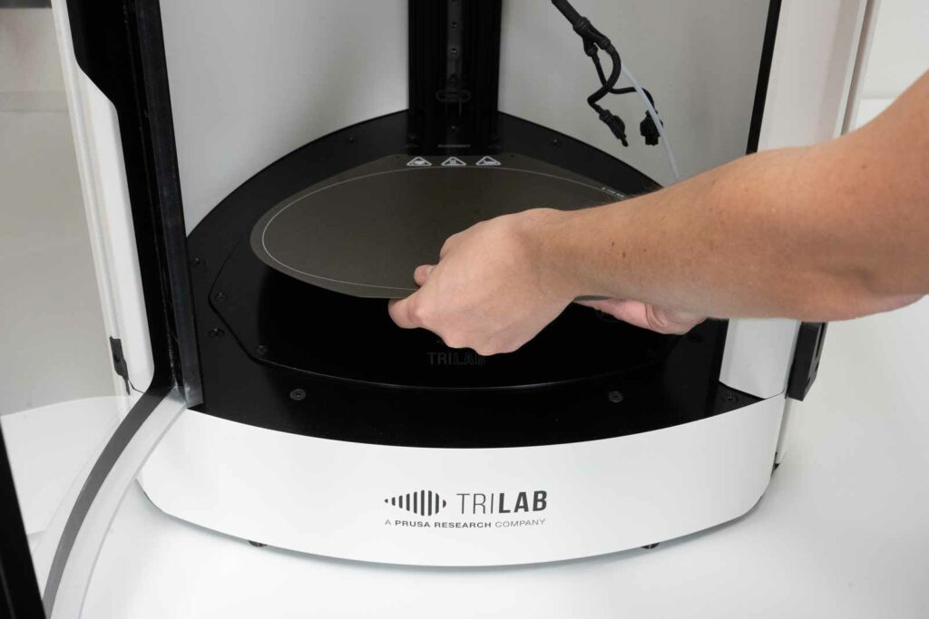
You will find a print pad in the lower fiam packaging.
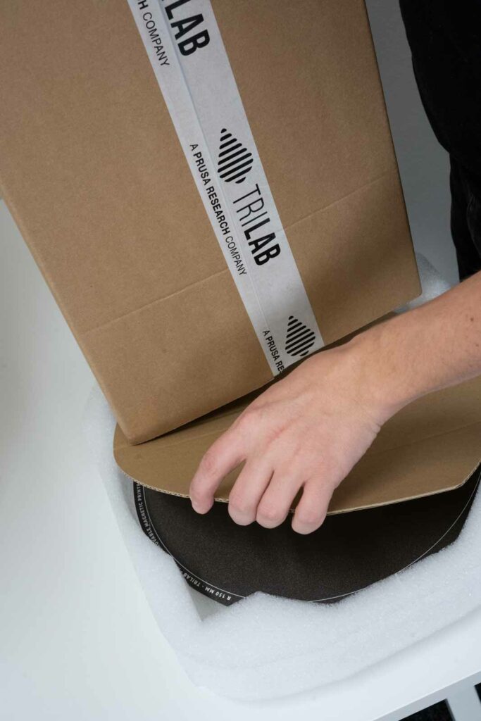
After cleaning the printpad from both sides and the printbed (black aluminum plate), you can place the printpad in the correct position using the cutout and spacer screws for the ALIGNMENT inscription.
2) Accessories
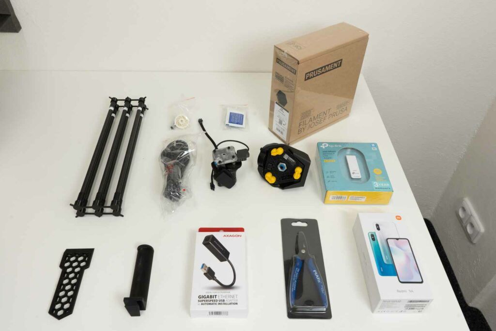
The box inside the printer contains standard accessories and necessary printer parts.
In each box there are:
- 6 magnetic carbon rods
- hex torque screw
- 10 cleaning tissues
- Prusament ASA Jet black
- power supply cable
- Titan extruder
- printhead
- wifi adapter
- scraper
- spoolholder
- ethernet adapter
- pliers
- DeltaControl display
3) Display installation
Place the phone in the charging cradle located on the right front profile of the printer.
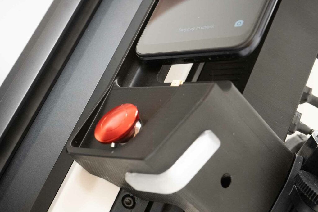
Warning: The only correct direction of positioning the display is vertically from above. Approaching in a different direction other than this may damage the charging cradle connector. Please use the same caution when removing the display.
You can tell the correct location of the display by clearly touching the display in the cradle and a light click (similar to connecting the chraging cable to the phone).
The display is stable after being placed in the cradle. But do not forget to remove it when transporting the printer.
4) Printhead installation
The printer is shipped with the carbon rods and printhead in the accessory box.
Tip: If you want to move the printer, the steps listed here can be done in reverse order to prepare the printer for transport.
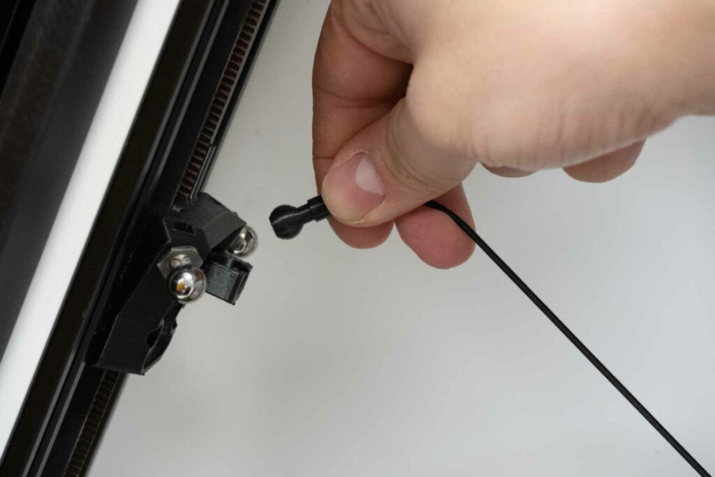
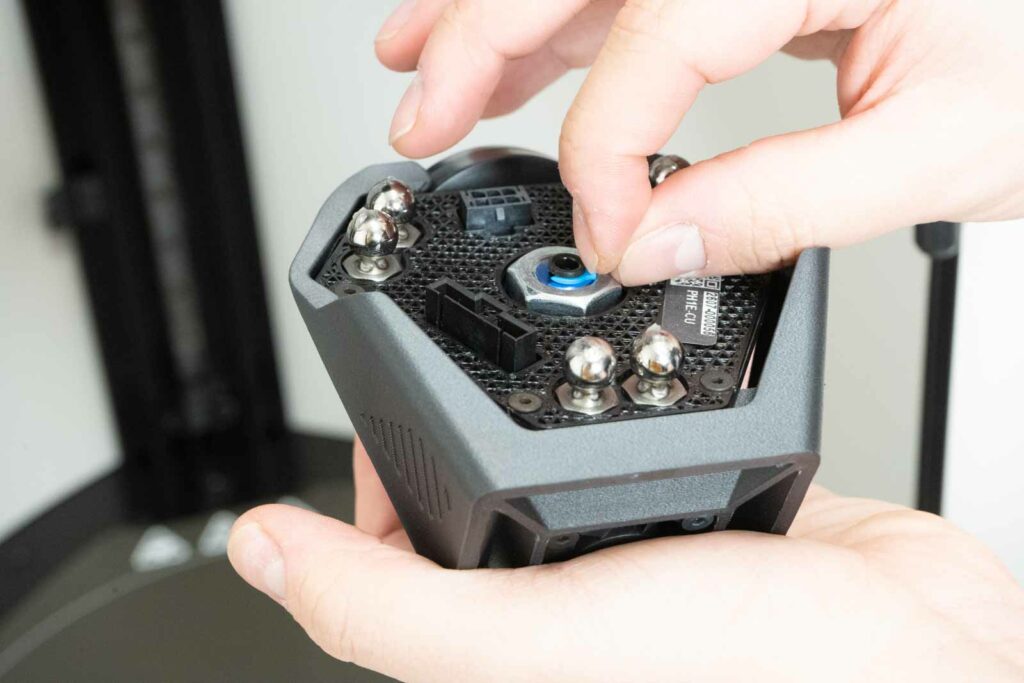
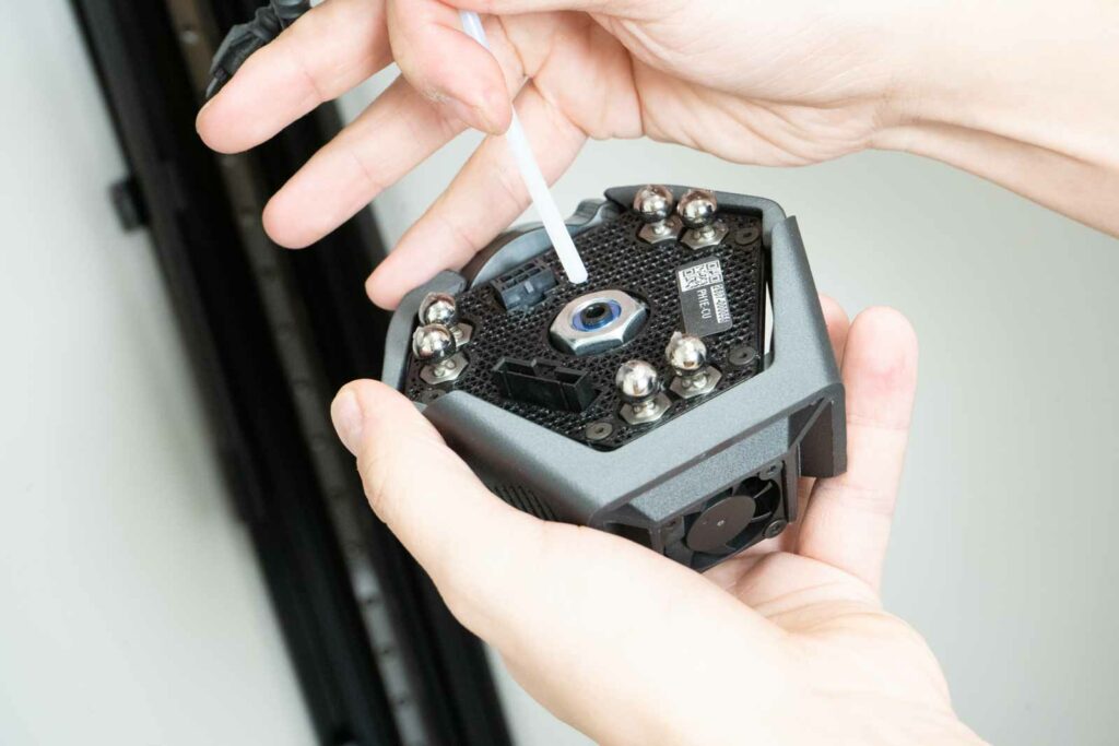
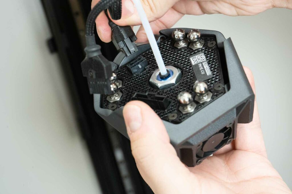
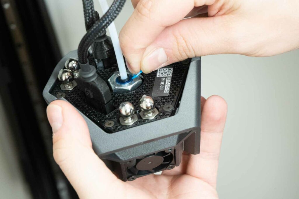
First, attach the spring ball of the cable centering system.
Carefully release the arms from the transport holder printed from flexible material.
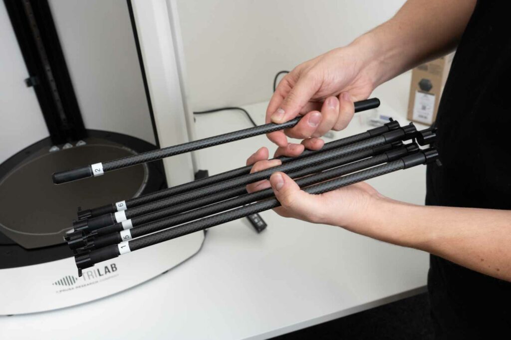
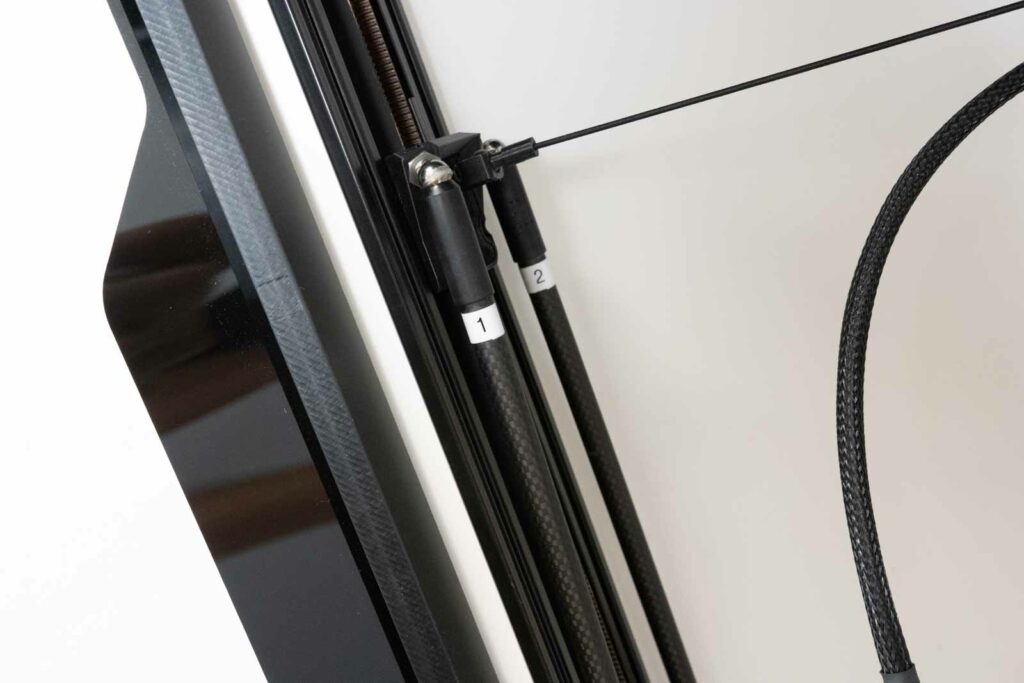
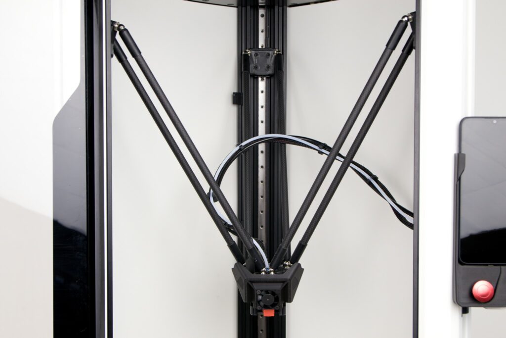
Carefully place the arms next to the magnetic joints in order 1-6 in a clockwise direction.
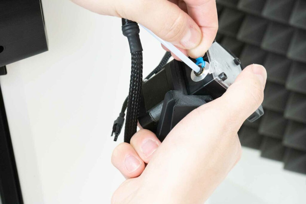
Next, remove the printhead from the box and carefully pull out the yellow transport covers.
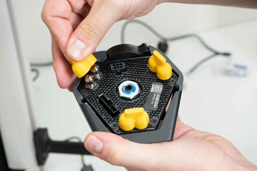
Take out the blue clip.
Insert the bowden fully into the printhead.
In the next step, very carefully connect the connectors, you must hear the click of their lock. Both are unique.
Put back the blue clip to secure the bowden.
Position the printhead so that the FRONT is facing you and gradually begin to fit the arms onto the magnetic joints while holding the printhead with your other hand.
Tip: We reccommend to start with the rear pair to have enough space for the manipulation.
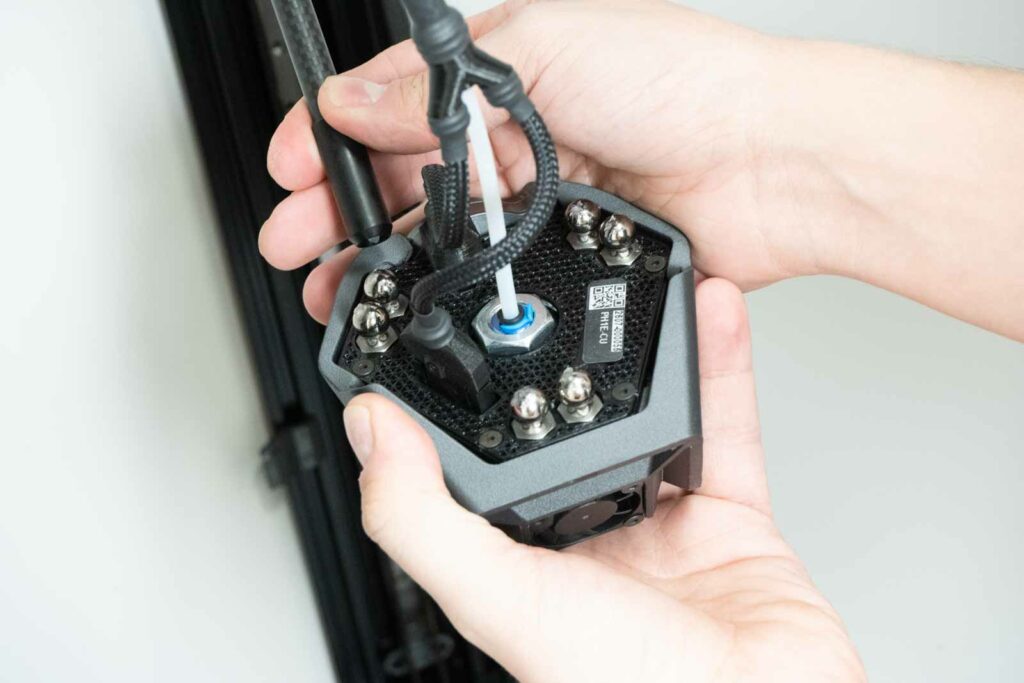
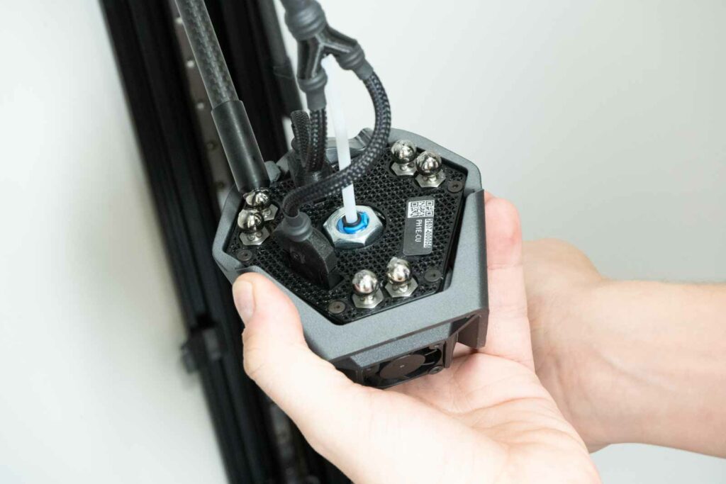
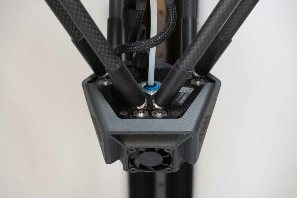
Warning: The cable harness must be routed between the rear and right pair of arms, as shown in the figure below.
Warning: Before releasing the printhead, check that all magnetic connections are secure by pulling gently.
5) Spoolholder
Place the spoolholder according to the figures below.
Check the correct position with your thumb.
6) Connectors
The goal of this part will be to connect all the connectors to the printer hub.
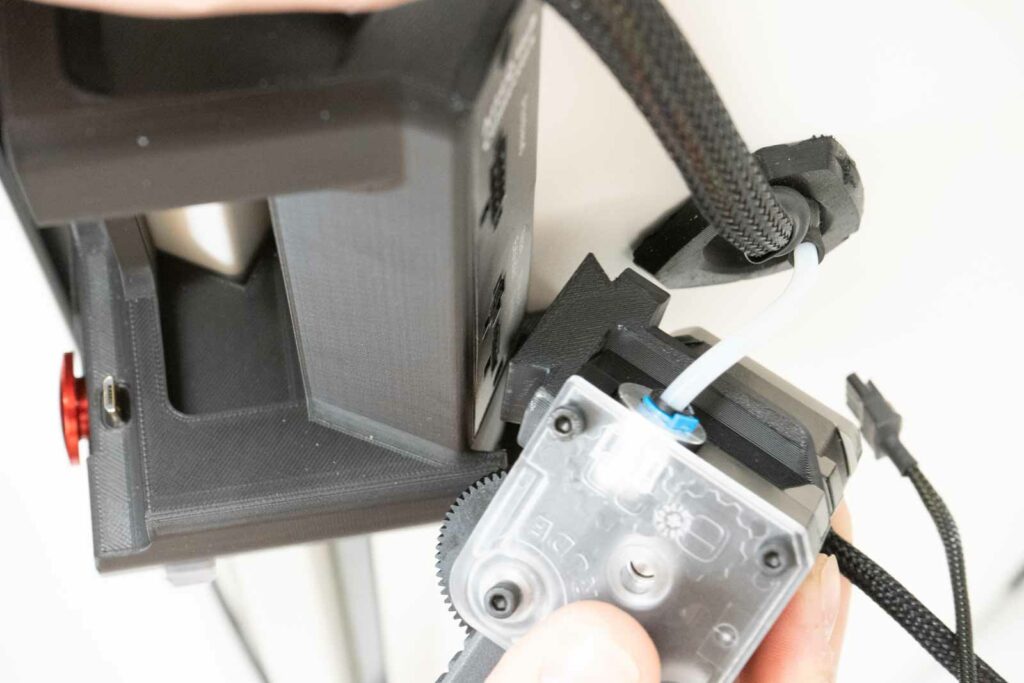
The extruder comes with a blue locking clip around the bowden grip. It needs to be removed (for a moment) before the next installation step. Simply pull the clip by the widened part.
Note: Keep the blue clip, you will need it.
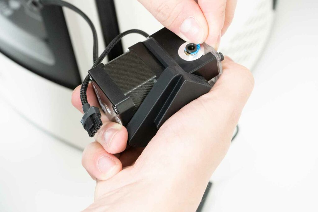
Now insert the bowden fully into the extruder.
Put the blue clip back onto the extruder.
Then insert the extruder into the corresponding recess in the hub. Place the extruder in the hub with a light push.
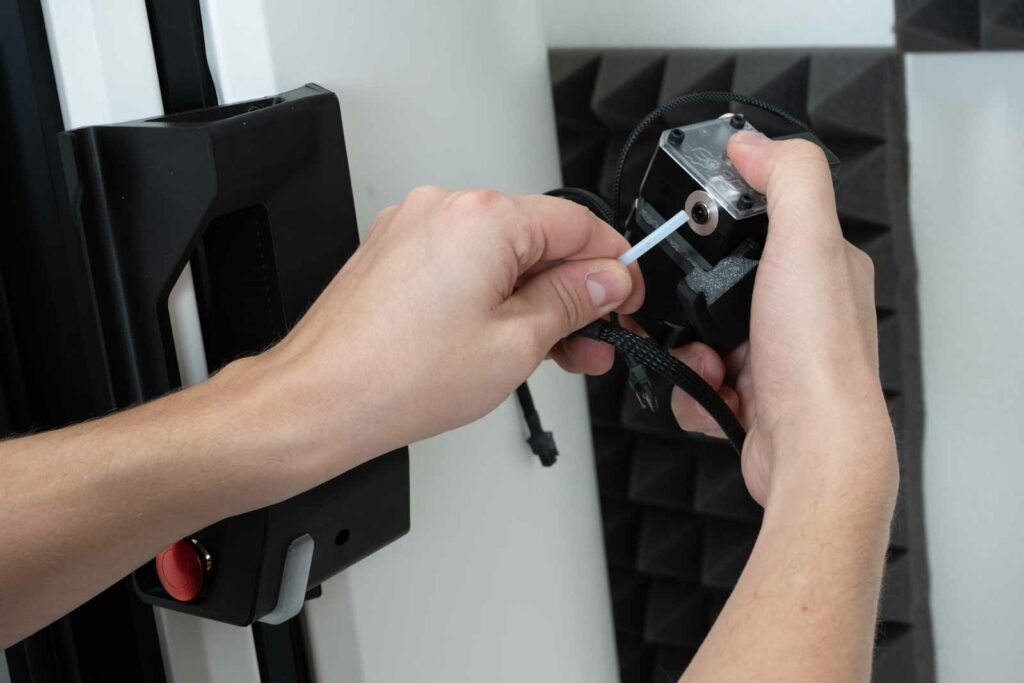
In this step, plug the connectors into the corresponding sockets according to their descriptions. All connectors are unique so they can be connected in only one way.
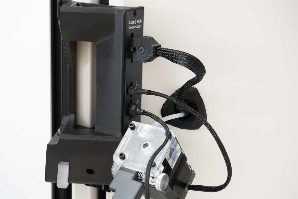
Warning: You must hear or feel a clear click when connecting all hub connectors. This is the only way to be sure that everything is properly connected.
7) Power supply
Warning: For customers in the EU, we deliver a supply set to 240 V as standard. For customers outside EU, we set the machine to the mode usual in their country.
Before plugging in the power cord, make sure the printer is turned off (rocker switch in zero position)
Connect the three-wire power cable to the power connector. The cable must be connected as far as it will go.
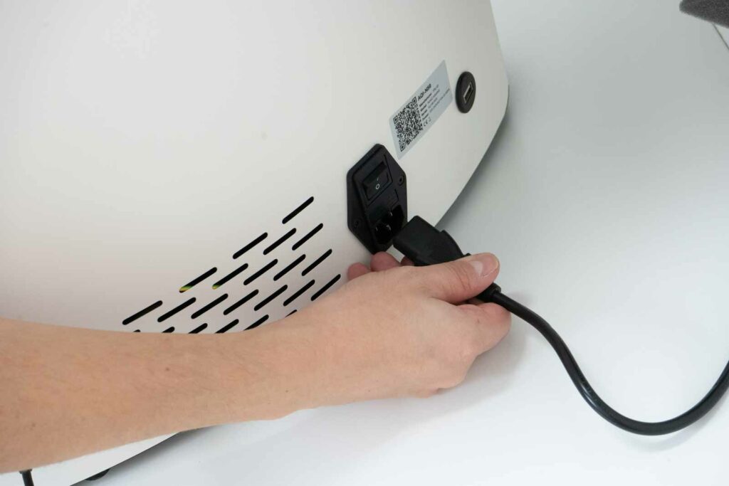
This was the last step in the printer self-installation.
Carefully check all connections, turn on the DeltaControl display by holding the side button and start the printer by the rocker switch.
8) First layer height
The AzteQ industrial printer calibration system consists of the physical contact of the nozzle with the printpad. Subsequent offset adjustments will therefore be minimal.
Before you start your first custom print, you need to set the correct first layer height. We reccomend not to underestimate this setting, a good first layer has a great influence on the adhesion to the printpad and the entire print of the model.
Note: Each material behaves a little differently when printing, and when changing the material, it may happen that the Z offset needs adjustment.
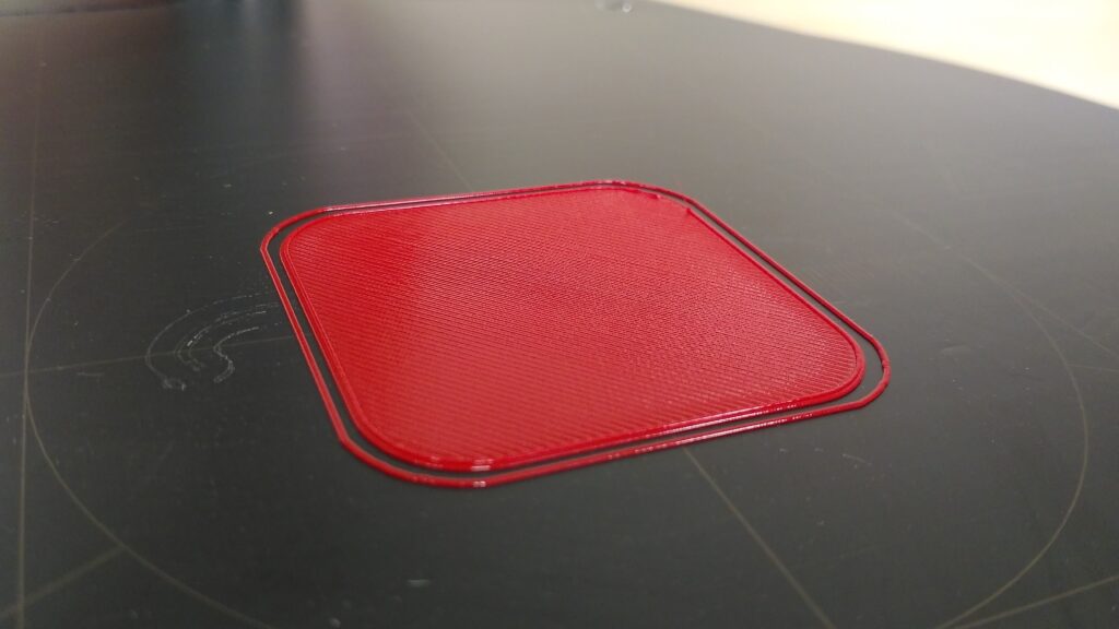
A well-adjusted first layer is smooth to the touch, looks unfirm, has no gaps between lines and outer perimeters.
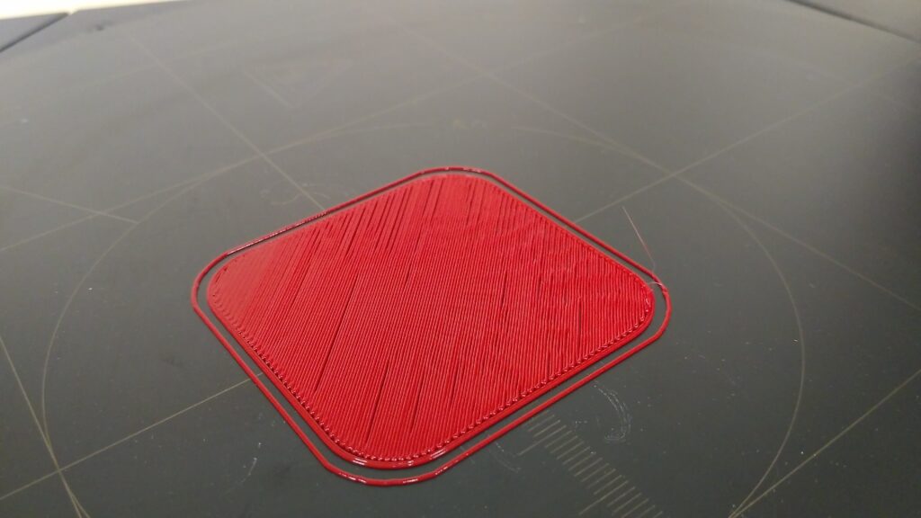
A layer that is too low has scratches in it cause by the nozzle movement and these scratches can be felt to the touch. If this situation occurs, in the DeltaControl application on the Tune tab, increase the Z-offset value using, for example, the +0.05 mm button.
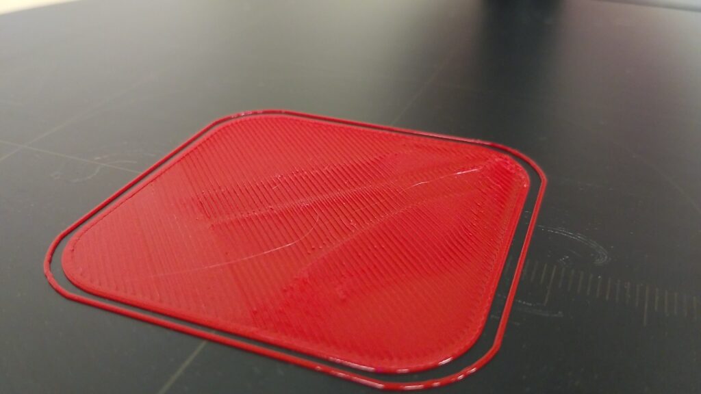
The opposite extreme, too high first layer, is typical by gaps between the lines, perimeters and poor adhesion. If this is happening, in the DeltaControl application in the Tune tab, reduce the Z-offset value, using, for example, the -0.0.5 mm button.
Warning: During the decreasing the Z-offset, be very careful not to reduce it too much, the nozzle could hit and scratch the printpad.